HUD_VerticalSpeed
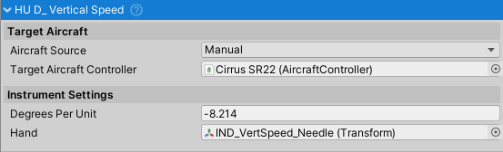
Purpose and Role
The HUD_VerticalSpeed instrument displays aircraft vertical speed (rate of climb/descent) on a variometer dial. It reads the vertical component of velocity from the aircraft controller, converts it to feet-per-minute, and rotates an indicator needle to show climb/descent rate. This instrument provides real-time feedback on altitude change rate for navigation and flight planning.
Data Source and Update Mechanism
The instrument continuously reads:
- Velocity.y from
AircraftController.Velocity(vertical speed, m/s) - Converts to feet-per-minute:
feetPerMinute = velocity.y * 196.85f - Updates every frame in
LateUpdate() - Clamps displayed rate to max indicated speed range
Configuration Properties
Hand (Transform) - The rotating vertical speed indicator needle
- Moves up for climb, down for descent
- Can be Transform (3D) or RectTransform (UI)
- Rotates around Z-axis based on climb rate
Degrees Per Unit (float) - Rotation degrees per 100 ft/min
- Default: -8.214 degrees per 100 ft/min
- Negative indicates counter-clockwise rotation
- Scaled by climb rate in 100 ft/min increments
Max Indicated Speed (float) - Maximum displayed climb rate in units of 100 ft/min
- Default: 20 (represents 2000 ft/min max)
- Typical range: 10-30 (1000-3000 ft/min max)
- Higher values allow display of higher climb rates
- Climb/descent rate clamped to this limit
Vertical Speed Measurement and Display
Vertical Speed Convention
Positive (climbing):
+1 m/s = +196.85 ft/min
+2 m/s = +393.7 ft/min
+5 m/s = +984.25 ft/min

Negative (descending):
-1 m/s = -196.85 ft/min
-2 m/s = -393.7 ft/min
-5 m/s = -984.25 ft/min
Needle Rotation Calculation
FeetPerMinute = Velocity.y * 196.85f
ClampedFPM = Clamp(FeetPerMinute, -maxIndicatedSpeed*100, +maxIndicatedSpeed*100)
HandRotation = ClampedFPM * degreesPerUnit * 0.01f
Example with defaults:
- Max indicated speed: 20 (2000 ft/min)
- degreesPerUnit: -8.214 degrees per 100 ft/min
- Climb 500 ft/min: Rotation = 500 * (-8.214) * 0.01 = -41.07°
- Descend 500 ft/min: Rotation = -500 * (-8.214) * 0.01 = +41.07°
Aircraft Source Configuration
- Manual Source (default) - Directly assign aircraft in inspector
- Vehicle Changer Source - Automatically switches to active vehicle
Setup Instructions
Basic Setup
- Create vertical speed indicator visual (dial showing ft/min scale)
- Create hand/needle showing climb/descent
- Assign hand Transform to Hand property
- Set Max Indicated Speed (20 typical for 2000 ft/min max)
- Set Degrees Per Unit (typically -8 to -10 for reasonable needle movement)
- Assign target aircraft controller
- Test by climbing/descending and observing needle movement
Calibration
- Level flight (zero vertical speed) - needle should be centered
- Steady climb - needle should move up proportionally
- Steady descent - needle should move down proportionally
- Maximum climb - needle approaches top limit
- Maximum descent - needle approaches bottom limit
- Adjust degreesPerUnit if needle movement too fast/slow
Public API
Properties (Read-only)
All properties configured in inspector.
Common Usage Patterns
Basic Climb Rate Monitoring
HUD_VerticalSpeed variometer = GetComponent<HUD_VerticalSpeed>();

// Automatically updates with aircraft vertical speed
// No additional code needed for basic operation
Climb Rate Limits
AircraftController aircraft = targetAircraftController;
float climbRateFtMin = aircraft.RateOfClimbFtMin;

// Warn if exceeding structural limits
if (Mathf.Abs(climbRateFtMin) > 4000f)
{
    // Excessive climb/descent rate - structural damage possible
    Debug.Log("WARNING: Excessive climb rate!");
}
Performance Monitoring
// Track best climb rate
float maxClimb = 0f;
float maxClimbSpeed = 0f;

void Update()
{
    float climb = targetAircraftController.RateOfClimbFtMin;
    if (climb > maxClimb)
    {
        maxClimb = climb;
        maxClimbSpeed = targetAircraftController.AirspeedKTS;
    }
}
Integration with Other Systems
- AircraftController - Source of vertical speed data
- VehicleChanger - Optional automatic aircraft source switching
- HUD_Instrument - Base class for instrument functionality
- Flight Planning - Can be used for altitude target management
- Autopilot - Can provide vertical speed commands
Real-World Context
Climb/Descent Rates
Typical aircraft vertical speeds:
- Slow climb: 100-300 ft/min
- Normal climb: 300-1000 ft/min
- Max climb: 1000-3000 ft/min (varies by aircraft)
- Slow descent: 100-300 ft/min
- Normal descent: 300-500 ft/min
- Emergency descent: 500-2000 ft/min
- Max descent: 2000-5000 ft/min possible
Variometer (Vario) Instrument
The variometer (vertical speed indicator) is used for:
- Altitude management - Monitoring climb/descent rates
- Fuel planning - Adjusting climb rate affects fuel burn
- Traffic avoidance - Maintaining assigned altitude
- Weather navigation - Finding better climb conditions
- Glider flying - Finding thermal updrafts (visual feedback)
Excess G Considerations
Rapid vertical speed changes can exceed aircraft structural limits:
- Positive G limit: Typical 3-6G depending on aircraft
- Negative G limit: Typical 2-3G (less than positive)
- Abrupt maneuvers can cause "G-loads" exceeding limits
- NWH system doesn't enforce these limits automatically
Troubleshooting
Needle Not Moving
- Verify hand Transform is assigned
- Check targetAircraftController is valid
- Confirm aircraft is climbing/descending (velocity.y != 0)
- Verify degreesPerUnit is not zero
Needle Movement Too Slow/Fast
- Adjust Degrees Per Unit value
- Typical range: -4 to -12 degrees per 100 ft/min
- More negative = more sensitivity
- Less negative = less sensitivity
Needle Inverted (up means down)
- Flip sign of Degrees Per Unit (-8.214 ↔ +8.214)
Needle Stuck at Maximum/Minimum
- Check max indicated speed setting
- If aircraft climbing/descending faster than max, increase maxIndicatedSpeed
- Verify climb rate is within reasonable bounds
Related Classes
HUD_Instrument- Base class for all flight instruments- AircraftController - Source of vertical speed data
- HUD_Airspeed - Airspeed display instrument
- HUD_Altimeter - Altitude display instrument
- HUD_Attitude - Pitch/roll attitude indicator
- HUD_Heading - Compass heading indicator
- HUD_Turn - Turn rate indicator
- Instruments - Base instrument functionality and overview