Wheel Controller 3D Manual
Setup
Warning: For WC3D to work properly, the vehicle model should have Unity-correct rotation and [1,1,1] scale. More about that here.
Vehicle Model
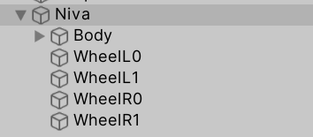
- Drag the model into the scene. The model should have correct rotation and 4 separated wheel meshes. This example will use the included Niva model.
- Example vehicle hierarchy:
- Add a Rigidbody to the vehicle and adjust the Mass to 1400.
- Attach a Collider to the vehicle. Collider is required for Rigidbody to work properly.
Wheels
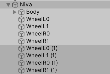
- Create empty GameObjects to hold the WheelController script. Position of this object will act as the suspension origin. These objects can be created by duplicating the wheel objects and stripping them of all the components, except for the Transform:
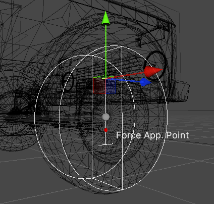
- Attach WheelController script to the newly created empty objects. If Gizmos are enabled, the vehicle should now show the suspension travel gizmos (white):
- WheelController > Target Rigidbody field should be automatically set to the earlier added Rigidbody (Niva in this case).
- Select each WheelController component and parent your wheel mesh to the Rotating Container Transform (automatically created as a child named "Rotating"). If you also have brake calipers or other non-rotating parts, parent them to the Non-Rotating Container (automatically created as "NonRotating").
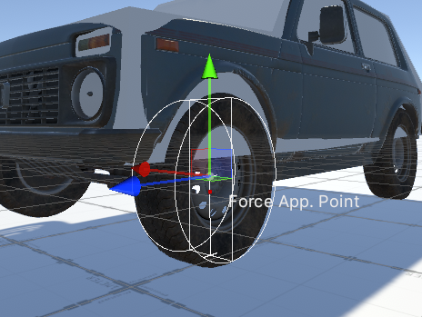
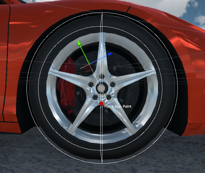
- The wheel gizmo now shows up. If the width or radius do not match the actual wheel width or radius, adjust the values manually.
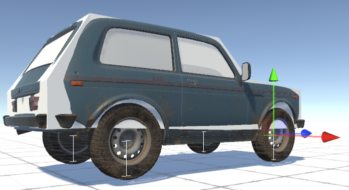
- After pressing play the vehicle should look something like the screenshot below:
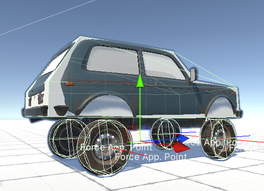
- Note the high ride height. To adjust this, grab the GameObjects containing the WheelController scripts and drag them up. The travel indicator (capital I) will move with the objects and indicates the top and bottom of the suspension travel:
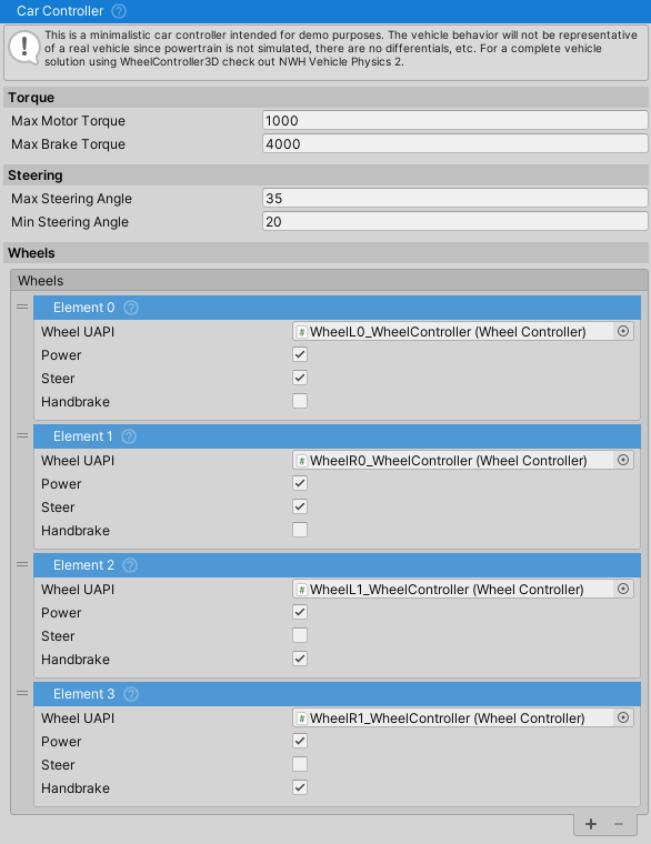
Car Controller
If using the WheelController3D standalone asset, use the provided CarController script. Otherwise, if using it as a part of the NWH Vehicle Physics 2 asset skip to the VehicleController quick start guide.
- Attach the CarController script to the vehicle.
- The wheels will be found automatically, but the Steer, Handbrake and Powered fields might need adjusting depending on the wheel order.
- Given that all the steps have been correctly followed, the vehicle will drive around normally at this point.
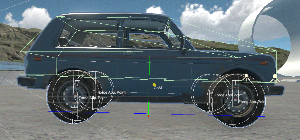
Variable Center of Mass
If the collider added previously is small (in relation to the size of
the vehicle) or offset, VariableCenterOfMass script can be used to adjust
the center of mass and inertia values of the vehicle.
Note: VariableCenterOfMass is part of NWH Common. For detailed information, see NWH Common - Variable Center of Mass.
- Center of mass gizmo should appear around the centre of the vehicle.
- Inertia for a typical car should be around [700, 1400, 400] or larger. Too low inertia causes jitter/floating of the vehicle, too high makes the vehicle feel like it is very heavy and resist rotation. Usually it is better to aim for larger value if this is suspect.
Adjusting the Behaviour
If you have no knowledge of how suspension works I would recommend checking out this link first. Also, check out the FrictionPreset page.
Tips
WheelControllerTransformrepresents the origin of the suspension. Its position directly affects the position of the suspension and the wheel. So, to raise the vehicle, lower theTransform, and vice versa. To achieve wider track (distance between wheels on the same axle), move theTransformoutwards. And finally, to achieve toe and caster angles, rotate theWheelControllerTransform. Example caster adjustment:
- Using very short spring rates might result in suspension bottoming out when wheel travel in one frame is larger than the total length of the spring. About 0.2m is the recommended minimum spring length value for default Time > Fixed Delta Time setting.
- Vehicles without suspension are supported. In that case a native MeshCollider will be used for collision, while the friction will still be calculated by the WheelController. To use a WheelController without a suspension, set the spring length to 0.
Reducing Roll
- The lower the center of mass is, the less roll the vehicle will have
in corners. If too low, the vehicle will start rolling in the opposite
direction than expected. The center of mass can be adjusted through
the
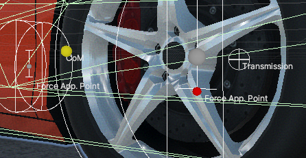
VariableCenterOfMassscript, or through theRigidbodyinspector in the newer versions of Unity. - Increase the Wheel Controller > Force Application Point Distance to a higher value. This is the point at which the friction forces will be applied, and value of 1 means one spring Max Length above the ground.
Achieving Oversteer
- Use a lower-grip FrictionPreset on the rear wheels (e.g., one with lower D parameter).
- Adjust Center of Mass forwards through the Variable Center of Mass script.
- Increase the spring rates on the rear wheels. Stiffer rear suspension, compared to front, generally results in more oversteer.
- Reduce the roll of the vehicle through the center of mass or the
Force Application Point Distance. Lower center of mass and higher force application point distance equals less roll, which in turn equals more oversteer.
Arcade-like Behavior
By default the asset is geared towards realism. To achieve arcade-like behavior:
- Create a custom FrictionPreset with modified parameters:
- Lower B (stiffness) to reduce tendency to snap oversteer (e.g., B=6-8 instead of 10)
- Adjust the curve to be more linear with a flatter peak
- Higher D (peak value) if you want more grip (e.g., D=1.2-1.5)
- Lower the center of mass to reduce the chance of vehicle flipping over and make vehicle lean less making it behave more like a go kart. Do not lower center of mass below the axle height or the vehicle might begin to lean in the opposite direction.
Considerations
While WheelController is quite flexible, there are a few things to keep in mind when designing a game around it. Most of these points apply to any wheel collider/controller that uses the inverse kinematics approach to wheel positioning, which positions the wheel on the ground and then calculates suspension forces. This approach results in good performance, stability, and reliability. Keep the following considerations in mind:
- Ground detection occurs over the entire bottom half of the wheel, but
not the top. Collisions on the top half of the wheel are handled by a
native MeshCollider. This means that wheels do not work when the
contact surface is on top of the wheel. Tips:
- It‘s a good idea for the vehicle body collider to cover the tops and sides of the wheels. However, in cases like a monster truck, it is perfectly fine for the wheels to stick out. * Ideally, driving on the vehicle side should be avoided as a game mechanic. * Due to potentially large suspension forces, it’s advisable to set the ’‘Other Body Force Scale’’ to <1. This reduces the forces applied to other Rigidbodies, preventing lightweight Rigidbodies from glitching out when the vehicle drives over them. Applying 5000N of force to a 20kg Rigidbody can cause issues for the physics solver.
- A pair of native
MeshColliders is used for handling edge cases and to prevent the wheel from ever clipping through another collider. There is aMeshCollidercovering the top half of the wheel, and one covering the bottom half. The top collider is constantly enabled and handles the side collisions, upside-down situations and otherwise hits to the top half or the side of the wheel. The bottom collider is only enabled when there is no suspension (the vehicle drives on the collider itself in that case), the vehicle bottoms out (as in the suspension can not produce enough force or has ran out of travel so the collider is enabled to prevent clipping into the ground) , or there is very high vertical velocity and there is a risk of vehicle clipping into the ground since the vertical distance the wheel travels in one physics update is larger than the radius of the wheel.
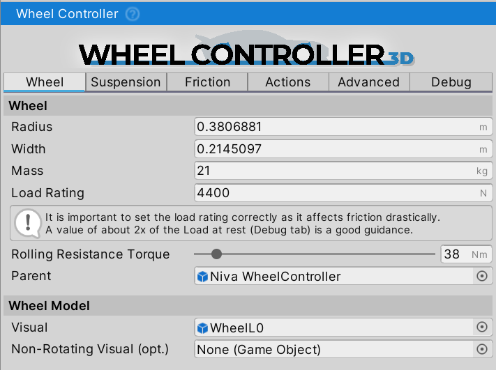
Field Explanations
Wheel
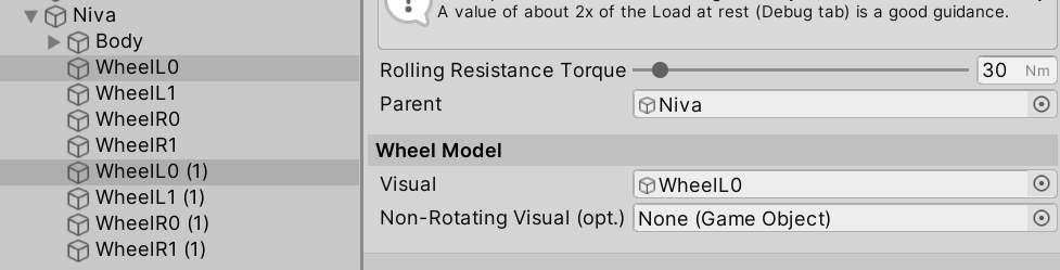
Radius- radius of the wheel in [m].Width- width of the wheel in [m].Mass- mass of the wheel in [m]. Only affects the wheel inertia. Does not affect the vehicleRigidbodymass.Rim Offset- lateral offset of the wheel rim from the suspension pivot point in [m]. Positive values move the wheel outward (wider track), negative values move it inward. This affects the steering pivot point and track width. Typical values: 0.03-0.06m for standard cars, 0.08-0.15m for wide body/stance builds.Load Rating- maximum load the tire is rated for, in [N]. A good rule of thumb is double the resting Debug => Suspension => Spring Force value. Otherwise, can be found through the tire load rating on the sidewall (check the Load Index here), theLoad Ratingwould be the value in kg multiplied by ~10).Rolling Resistance Torque- torque in [Nm] that will constantly be applied as a brake torque to the wheel, and represents the rolling resistance of the tire due to the deformation and other factors. Higher value will result in vehicle stopping sooner when free-rolling.Target Rigidbody- theRigidbodythat the forces will be applied to.Rotating Container- aTransformthat holds all rotating parts (wheel mesh, brake discs, etc.). Automatically created as "Rotating" child if not assigned. Place your wheel mesh as a child of this container. The mesh/model must have a correctly centered pivot and Unity rotation (Z-forward, Y-up, X-right). This container handles wheel spin rotation, suspension movement, steering angle, and camber angle.Non-Rotating Container- aTransformthat holds parts that move with suspension but don't rotate with the wheel (brake calipers, fenders, suspension components, etc.). Automatically created as "NonRotating" child if not assigned. This container follows suspension movement and steering but doesn't spin with the wheel.
Suspension
Info: Suspension settings are fully based on physics, so the general car suspension principles also apply here.
For best results, it is recommended to have the spring length higher than the Project Settings > Time > Fixed Delta Time setting. Lower values, or even 0, are supported but might result in bottoming out of the suspension which will result in a harsh and jumpy ride over bumps. The state of the suspension can be seen under the Debug tab during runtime (bottomed out / normal / fully extended).
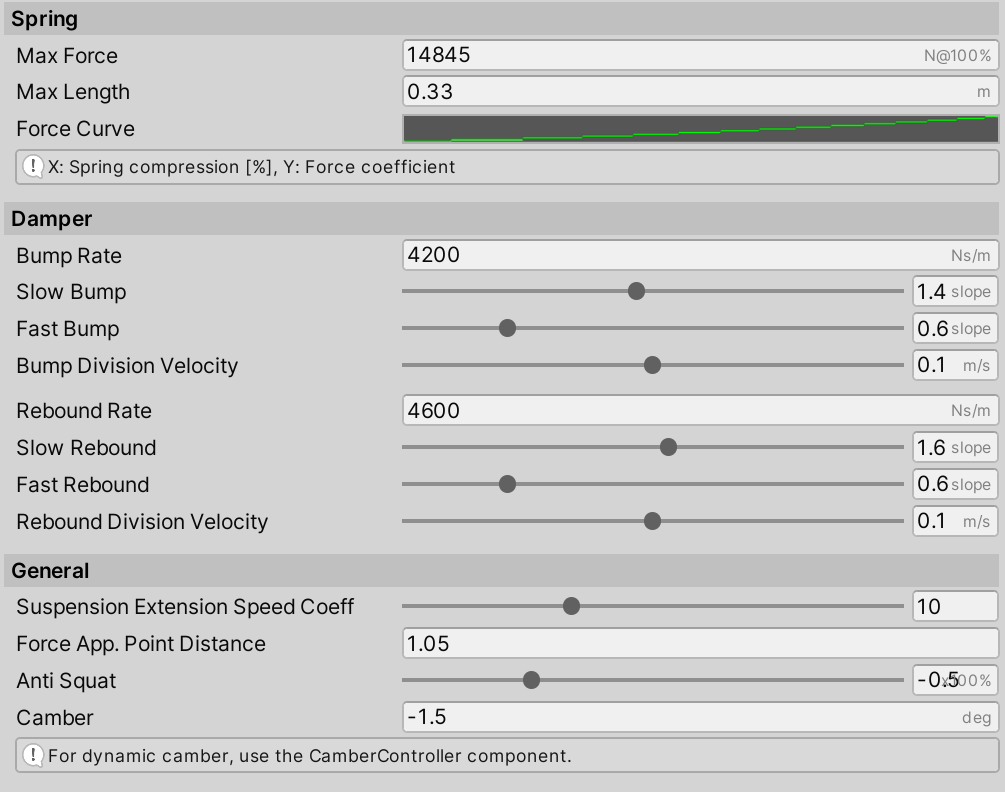
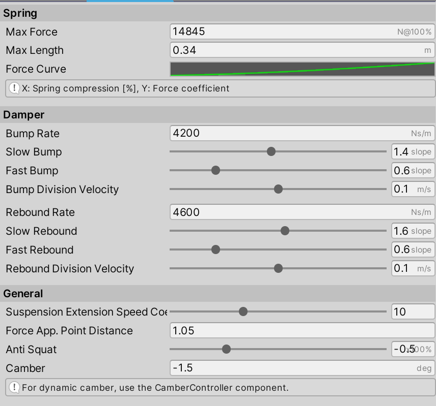
Spring
Max Force- the maximum force the spring can exert. This force will be used when the spring is fully compressed (spring length equals zero).- The value of
Max Forceshould be adjusted so that the suspension rests at 30% compression (spring length is 30% of the max spring length, this can be checked through the Debug tab during runtime). - Damper bump and rebound values should be used after the spring is
adjusted to make the suspension stiffer and less ‘bobby’, not the
spring
Max Force.
- The value of
Max Length- maximum suspension length. Suspension extends in the -Y direction of theWheelControllerTransformand is represented by a capital letter "I" white gizmo.- To adjust the ride height do not change the spring length (except in
cases where longer suspension travel is needed), instead, adjust the
Y position of the
WheelControllerTransforminstead.
- To adjust the ride height do not change the spring length (except in
cases where longer suspension travel is needed), instead, adjust the
Y position of the
Progressiveness- defines how the spring force changes with compression.- 1.0 = Linear spring (force increases proportionally with compression)
- < 1.0 = Digressive (softer when compressed, comfort-oriented)
-
1.0 = Progressive (stiffer when compressed, performance/racing) Common values: 0.5-0.8 for comfort, 1.0 for balanced, 1.2-2.0 for racing.
Damper
The damper (shock absorber) controls suspension oscillation and movement speed, working with the spring to provide controlled suspension behaviour. It uses a dual-speed system with different damping rates for slow and fast movements.
Base Rates:
Bump Rate- damping rate in Ns/m when the suspension is getting compressed (bump). Force applied per unit of compression velocity. Higher values make the suspension stiffer when climbing obstacles or going over bumps.- Too high will result in harsh impacts and vehicle jitter.
- 5% to 20% of the spring
Max Forceis a good starting point. - Typical values: Comfort 1000-2000, Sport 2000-4000, Race 3000-6000 Ns/m.
Rebound Rate- damping rate in Ns/m when the suspension is getting extended (rebound). Force applied per unit of extension velocity. Higher values make the suspension take longer to relax after getting compressed.- Too high will result in suspension packing down and vehicle jitter.
- Usually equal to or slightly higher than Bump Rate (within +/-50%).
- Typical values: Comfort 1000-2500, Sport 2500-4500, Race 4000-7000 Ns/m.
Dual-Speed Coefficients:
The damper switches between slow and fast damping based on suspension velocity. Slow damping controls body motion during normal driving (cornering, braking), while fast damping handles impacts from bumps and rough terrain.
Slow Bump- coefficient for low-speed compression (below Bump Division Velocity). Controls body roll and dive during cornering and braking.- 0.8-1.2: Comfort-oriented, allows more body movement
- 1.2-1.6: Balanced control (default range)
- 1.6-2.5: Sport/race, minimal body movement
Fast Bump- coefficient for high-speed compression (above Bump Division Velocity). Controls impact absorption when hitting bumps, curbs, or rough terrain.- 0.3-0.6: Soft, absorbs impacts well (comfort/off-road)
- 0.6-1.0: Balanced road use
- 1.0-2.0: Stiff, maintains platform control (racing)
Slow Rebound- coefficient for low-speed extension (below Rebound Division Velocity). Controls how quickly the vehicle returns to neutral after weight transfer.- 1.0-1.4: Quick return, responsive feel
- 1.4-1.8: Balanced control (default range)
- 1.8-2.5: Slow return, stable platform
- Should be slightly higher than Slow Bump to prevent oscillation
Fast Rebound- coefficient for high-speed extension (above Rebound Division Velocity). Controls how fast the wheel returns after compression. Affects tire contact on rough surfaces.- 0.3-0.6: Quick return, maintains tire contact on rough terrain
- 0.6-1.0: Balanced control
- 1.0-2.0: Slow return, reduces oscillation but may lose contact
- Match or slightly exceed Fast Bump for stability
Division Velocities:
Bump Division Velocity- threshold velocity [m/s] where bump damping switches from slow to fast response. Below this: body motion control. Above this: bump absorption.- Lower values (0.02-0.04): Earlier transition, softer over bumps
- Higher values (0.08-0.15): Later transition, more body control
- Default 0.06 works well for most road vehicles
Rebound Division Velocity- threshold velocity [m/s] where rebound damping switches from slow to fast response. Below this: controlled body motion. Above this: rapid extension after bumps.- Typically slightly lower than Bump Division Velocity
- Lower values: Better tire contact on rough surfaces
- Higher values: More controlled body motion
Camber
Camber- fixed camber angle in degrees. A negative value will result in the top of the wheel being rotated towards the vehicle, and vice-versa.Camber Curve- curve representing spring compression (0 to 1) on X-axis and camber angle on Y-axis. When enabled viaUse Camber Curve, camber will automatically adjust based on suspension travel. This replaces the need for the oldCamberControllerscript.Use Camber Curve- enables the camber curve. When disabled, camber can be set manually or controlled externally (e.g., by solid axle suspension in NWH Vehicle Physics).
Friction
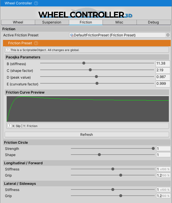
WheelController uses a preset-based friction system powered by the Pacejka Magic Formula tire model. Instead of configuring friction parameters per-wheel, you assign a FrictionPreset ScriptableObject that defines the tire's friction characteristics.
Active Friction Preset
Active Friction Preset- the currently active FrictionPreset ScriptableObject that defines the tire's friction curve. This preset contains the Pacejka BCDE parameters that determine how the tire generates grip at different slip ratios.- You can create different presets for different tire types (street, sport, racing, off-road, etc.)
- Presets can be swapped at runtime to simulate surface changes (asphalt, gravel, ice, mud)
- Default preset is located at
Resources/Wheel Controller 3D/Defaults/DefaultFrictionPreset - To create a new preset: Right-click in Project window > Create > NWH > Vehicle Physics 2 > Friction Preset
Understanding Friction Presets
FrictionPreset ScriptableObjects contain the Pacejka Magic Formula parameters that define the friction curve:
- B (Stiffness Factor) - controls initial slope and tire response (10-20 typical)
- Higher B: More responsive, sharper peak (sports tires)
- Lower B: Softer response, wider peak (comfort tires)
- C (Shape Factor) - defines curve shape (1.3-1.8 typical)
- Higher C: Taller, narrower peak
- D (Peak Value) - maximum friction coefficient (0.8-1.2 typical)
- Higher D: More overall grip (racing slicks)
- Lower D: Less grip (wet/ice conditions)
- E (Curvature Factor) - controls falloff shape (0.9-1.0 typical)
- E near 1.0: Gradual falloff
- E < 1.0: Sharper falloff
The preset automatically generates an AnimationCurve from these parameters. The X-axis represents slip (0-1), and the Y-axis represents the friction coefficient.
Common Friction Preset Examples
- Dry Asphalt: B=10, C=1.6, D=1.0, E=0.98 - Balanced grip, sharp rise, gradual falloff
- Race Slick: B=15, C=1.8, D=1.3, E=0.95 - High grip, very sharp response
- Wet Road: B=8, C=1.5, D=0.75, E=1.0 - Reduced grip, softer response
- Gravel: B=7, C=1.4, D=0.7, E=1.0 - Moderate grip, gradual falloff
- Ice: B=5, C=1.3, D=0.2, E=1.0 - Very low grip, very soft response
Changing Friction at Runtime
You can change the active friction preset through code to simulate different surfaces:
// Example: Change friction when entering a different surface
WheelController wheel = GetComponent<WheelController>();
wheel.activeFrictionPreset = icePreset; // Assign a different FrictionPreset
For more details on FrictionPreset parameters and tuning, see the FrictionPreset documentation.
Static Friction System
The friction system includes a static friction mode for low-speed stability. When a wheel's velocity drops below a threshold, it switches from slip-based dynamic friction to a spring-damper anchoring system that prevents jitter and drift at rest.
Key Parameters:
Static Friction Strength- Master switch (0-1). Set to 0 to disable static friction entirely.Static Friction Damping- Damping ratio for the anchor spring. 1.0 = critical damping (no overshoot).Static Friction Speed Threshold- Velocity (m/s) below which static mode engages. Default 0.3 m/s.Static Friction Hysteresis- Multiplier for exit threshold to prevent oscillation between modes. Default 1.2x.Static Break Threshold- Force multiplier required to break out of static mode. Default 1.5x max grip.Static Friction Cooldown Frames- Frames to wait before static can re-engage after breaking. Default 10.Static Longitudinal Stiffness- Spring stiffness for braking direction. Default 800.Static Lateral Stiffness- Multiplier of longitudinal stiffness for sideways direction. Default 1.0.
The static friction system also includes slope compensation to prevent vehicles from drifting on inclines when stopped.
Advanced Friction Parameters
The StandardFriction component (automatically added with WheelController) provides additional tuning:
Grip(Vector2) - Force multiplier. X=longitudinal (acceleration/braking), Y=lateral (cornering). Default [1.0, 0.95].Stiffness(Vector2) - Slip sensitivity multiplier. Higher values = more responsive. Default [1.0, 0.8].Load Sensitivity(Vector2) - How friction scales with load. 1.0=linear, <1.0=diminishing returns (realistic). Default [0.85, 0.8].
WheelHit
The WheelHit struct contains detailed information about the wheel's contact with the ground.
It's updated every physics frame and is only valid when WheelController.isGrounded is true.
All vectors are in world space unless specified as "local".
Available fields:
collider- the Collider component that the wheel is in contact with. Null when airborne. Used for surface type detection, terrain texture sampling, and triggering surface-specific effects.normal- surface normal vector at the contact point in world space. Points away from the surface. Used for calculating suspension force direction and determining surface angle.localNormal- surface normal in wheel local space, relative to the wheel's coordinate system.point- exact contact point between wheel and ground in world space. Used for applying forces and spawning particle effects.localPoint- contact point in wheel local space. Used internally for suspension compression calculations.contactVelocity- relative velocity between wheel and contact surface in m/s. This is the actual slip velocity used for friction calculations. Zero when wheel and surface move together (perfect grip).hitRigidbodyVelocity- velocity of the contacted Rigidbody at the hit point. Zero for static objects. Used for moving platform support and dynamic object interaction.hitRigidbody- the Rigidbody component of the contacted object. Null for static geometry. Forces are only applied if this is not null andotherBodyForceScale> 0.
Example usage for surface detection:
WheelController wheel = GetComponent<WheelController>();
if (wheel.isGrounded && wheel.wheelHit.collider != null)
{
    // Check surface type by tag
    if (wheel.wheelHit.collider.CompareTag("Gravel"))
    {
        // Apply gravel friction preset or spawn dust particles
    }

    // Get surface angle
    float slopeAngle = Vector3.Angle(Vector3.up, wheel.wheelHit.normal);
}
Ground Detection
WheelController uses the StandardGroundDetection component for detecting ground contact.
This component provides two detection modes with different performance/accuracy trade-offs:
- Sphere Cast - single wide sphere cast from wheel center. Faster (~0.02ms per wheel) but less accurate on complex terrain. Best for AI vehicles, mobile platforms, or arcade games where performance is critical.
- Multicast - multiple sphere casts distributed across the wheel circumference. Most accurate (~0.03-0.05ms per wheel), handles all terrain types including curbs, rocks, and uneven surfaces. Recommended for player vehicles, off-road games, and sim racing.
The cast type can be changed in the StandardGroundDetection component inspector or at runtime:
StandardGroundDetection groundDetection = GetComponent<StandardGroundDetection>();
groundDetection.castType = StandardGroundDetection.CastType.Sphere; // or Multicast
Misc
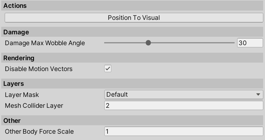
A collection of unsorted fields and actions.
Actions
- Position To Visual positions the
WheelControllerTransformexactly above theVisualTransformposition, with the estimated suspension travel.
Multiplayer
Visual Only Updatemakes the wheel follow the ground, but not update any physics. This is useful for cases where the vehicle needs to be moved around with the wheels still rotating, e.g. dumbly following a path or being a client vehicle that is not updating the physics.
Rendering
Disable Motion Vectorsmakes the motion blur not apply to the wheels, which avoids glitching that would otherwise happen with Post Processing package.
Layers
Layer Maskadjusts the layers which will be detected by the wheel.Mesh Collider Layer- layer that will be assigned to a MeshCollider that is used for handling edge cases (such as dropping from height, side impacts, no-suspension situations). Check the Considerations section for an explanation of why WC3D uses a MeshCollider.
Other
Other Body Force Scalescales the force applied to the hit Rigidbody. This can be useful in cases of interaction with lighter-weight Rigidbodies, as only a fraction of the suspension and friction forces is applied to the hit Rigidbody, avoiding the physics solver from glitching out. Applying 5000N of force to a 5kg Rigidbody will result in that Rigidbody most likely flying into the air, so using a value less than 1 for force scale can be helpful in avoiding this while still keeping the interaction between the two. Can also be set to 0 to not apply any forces to other Rigidbodies.Use Contact Modification- experimental feature that uses Unity's contact modification API to soften collisions in the wheel's forward direction. This helps vehicles drive over small obstacles and curbs more smoothly by reducing harsh impact forces. May cause wheels to clip through thin objects if not configured properly. Enabled by default.Implicit Damping- enables implicit integration for the damper force calculation. This helps prevent suspension jitter at lower physics update rates (e.g., 50Hz) by improving numerical stability. Recommended to leave enabled unless you're running at very high physics rates (200Hz+).Auto Calculate Load Smoothing Factor- when enabled, automatically calculates the load smoothing factor based on the vehicle's center of mass height. Higher CoM vehicles get lower smoothing factors for better stability. Disable to set the value manually.Load Smoothing Factor- temporal smoothing applied to wheel load before friction calculations. Prevents high-frequency load oscillations from causing jitter. Range 0.3-0.9.- Higher values (0.6-0.7): More responsive, suitable for low CoM vehicles (sports cars)
- Lower values (0.4-0.5): Smoother, suitable for high CoM vehicles (trucks, SUVs)
- When
Auto Calculate Load Smoothing Factoris enabled, this is set automatically:- CoM ≤ 0.0m above wheels → 0.7 (responsive)
- CoM 0.5m above wheels → 0.6 (balanced)
- CoM 1.0m above wheels → 0.5 (stable)
- CoM ≥ 1.5m above wheels → 0.4 (very stable)
Force Feedback
WheelController provides properties for steering wheel force feedback integration:
Aligning Moment- Self-aligning torque from tire deformation in Nm. This is the torque that tries to return the steering to center. Use this value for steering resistance/weight in force feedback implementations. Positive values push right, negative push left.Tire Scrub- Tire scrub intensity from 0 to 1. Represents the amount of lateral slip occurring at the contact patch. Use this for vibration/rumble effects when the tire is sliding.
WheelController frontLeft = GetComponent<WheelController>();
WheelController frontRight = ...;

// Calculate combined steering feel from front wheels
float steeringTorque = (frontLeft.aligningMoment + frontRight.aligningMoment) * 0.5f;
float scrubIntensity = Mathf.Max(frontLeft.tireScrub, frontRight.tireScrub);

// Apply to force feedback device
ffbDevice.SetTorque(steeringTorque * torqueScale);
ffbDevice.SetVibration(scrubIntensity * vibrationScale);
Substepping
WheelController uses a high-frequency substepping system to improve physics stability and accuracy. Instead of running wheel physics once per FixedUpdate, the system runs multiple substeps per frame, allowing for more accurate tire forces and smoother suspension behavior.
WheelControllerManager
The WheelControllerManager is a singleton that orchestrates all wheel physics. It automatically creates itself when any WheelController is enabled.
Target Effective Rate- Target physics rate in Hz (default: 200Hz). The manager automatically calculates how many substeps are needed based on Unity'sfixedDeltaTime. For example:- At 50Hz physics (0.02s fixedDeltaTime): 4 substeps → 200Hz effective rate
- At 100Hz physics (0.01s fixedDeltaTime): 2 substeps → 200Hz effective rate
Higher effective rates provide:
- More stable friction calculations at high speeds
- Smoother suspension response over rough terrain
- Better tire grip modeling during rapid weight transfers
- More accurate vehicle dynamics during aggressive driving
The substep count is automatically clamped between 1 and 8.
Per-Vehicle Substepping
Wheels are grouped by their parent Rigidbody. Each group can have an independent effective rate override set through the WheelControllerGroup.targetEffectiveRateOverride property. This allows:
- Player vehicles to run at higher rates for better feel
- AI or distant vehicles to run at lower rates for performance
- Sleeping vehicles to skip processing entirely
Powertrain Integration
When used with NWH Vehicle Physics 2, the powertrain solver runs at the same substep rate as the wheels. This is achieved through the ISubstepCallback interface:
// VehicleController implements ISubstepCallback
public void OnBeforeSubstep(float substepDt, WheelControllerGroup group)
{
    // Powertrain runs at wheel substep frequency
    powertrain.engine.IntegrateDownwards(substepDt);
}
This ensures torque calculations respond to wheel state changes at each substep rather than once per frame, resulting in more accurate power delivery and smoother acceleration.
Anti-Roll Bar (ARB)
The anti-roll bar (also called sway bar or stabilizer bar) reduces body roll during cornering by transferring load between wheels on the same axle.
Configuration
Each WheelController has ARB parameters that work per-axle (wheel pairs are automatically detected):
ARB Stiffness- Anti-roll bar stiffness in N/m. Higher values reduce body roll but can make the vehicle feel stiffer. Typical values:- Comfort vehicles: 5,000 - 15,000 N/m
- Sport vehicles: 15,000 - 30,000 N/m
- Race vehicles: 30,000 - 60,000 N/m
- Set to 0 to disable ARB for this axle
ARB Damping- Damping coefficient to prevent oscillation. Typical values are 10-30% of stiffness. Too low causes oscillation, too high makes the bar feel sluggish.
How It Works
The ARB system:
- Automatically pairs left/right wheels on each axle based on position
- Measures suspension compression difference between paired wheels
- Applies corrective torque to resist roll (transfers load to the more compressed side)
A stiffer rear ARB relative to front promotes oversteer (rear breaks traction first). A stiffer front ARB promotes understeer. Adjusting ARB balance is a key tool for tuning vehicle handling characteristics.
Scripting
ARB parameters can be adjusted at runtime:
WheelController wheel = GetComponent<WheelController>();
wheel.arbStiffness = 20000f; // N/m
wheel.arbDamping = 4000f;    // Ns/m
Stability Control (ABS/TCS)
WheelController includes per-wheel stability control settings for Anti-lock Braking System (ABS) and Traction Control System (TCS). These systems help maintain vehicle stability during aggressive braking and acceleration.
ABS Configuration
Anti-lock Braking prevents wheel lock-up during hard braking by modulating brake pressure:
ABS Enabled- Master switch for anti-lock braking on this wheel.ABS Slip Threshold- Slip ratio at which ABS begins intervention. Default 0.15 (15% slip). Higher values allow more slip before intervention, lower values intervene earlier.ABS Slip Range- Slip range over which ABS modulates. Default 0.15. The system will target slip between (threshold) and (threshold + range).
TCS Configuration
Traction Control prevents wheel spin during acceleration by limiting engine torque:
TCS Enabled- Master switch for traction control on this wheel.TCS Slip Threshold- Slip ratio at which TCS begins intervention. Default 0.10 (10% slip). Lower than ABS threshold since wheelspin is detected earlier.TCS Max Counter Torque Ratio- Maximum counter-torque as a fraction of applied motor torque. Default 0.8. A value of 0.8 means TCS can reduce up to 80% of the applied torque.TCS Max Counter Torque- Absolute maximum counter-torque in Nm. Default 3000 Nm. Caps the counter-torque regardless of motor torque applied.
Runtime Flags
These read-only properties indicate when stability systems are actively intervening:
absActive- True when ABS is currently reducing brake torque.tcsActive- True when TCS is currently limiting motor torque.tcsCounterTorque- The counter-torque being applied by TCS this frame [Nm].
WheelController wheel = GetComponent<WheelController>();

// Configure stability control
wheel.stabilityControl.absEnabled = true;
wheel.stabilityControl.absSlipThreshold = 0.12f;
wheel.stabilityControl.tcsEnabled = true;
wheel.stabilityControl.tcsSlipThreshold = 0.08f;

// Check intervention status (useful for dashboard indicators)
if (wheel.absActive)
{
    // Show ABS warning light
}
if (wheel.tcsActive)
{
    // Show TCS warning light
}
Note: When using WheelController with NWH Vehicle Physics 2, the vehicle-level ABS/TCS modules take precedence. These per-wheel settings are primarily for standalone WC3D usage.
Debug
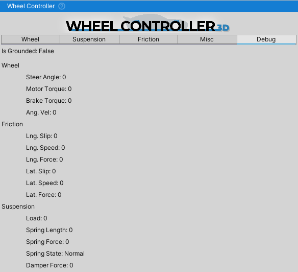
An overview of the WheelController values. It can be helpful in setting up the suspension travel or checking if the suspension bottomed out when going over a bump or landing a jump.
As always, the debug values can also be seen through right clicking the Inspector tab and switching the inspector into the Debug mode.