Vehicle Controller Manual
Before starting with detailed vehicle setup it is recommended to check out the Quick Start guide, as this page assumes a minimal working setup has been done.
VehicleController is attached to the vehicle root, alongside its Rigidbody. Work through the sections below to configure the vehicle, or use the chapter links to return to a particular setting. The engine, clutch, transmission and wheels are covered together under Powertrain, followed by sound, effects, surfaces, controls and optional modules.
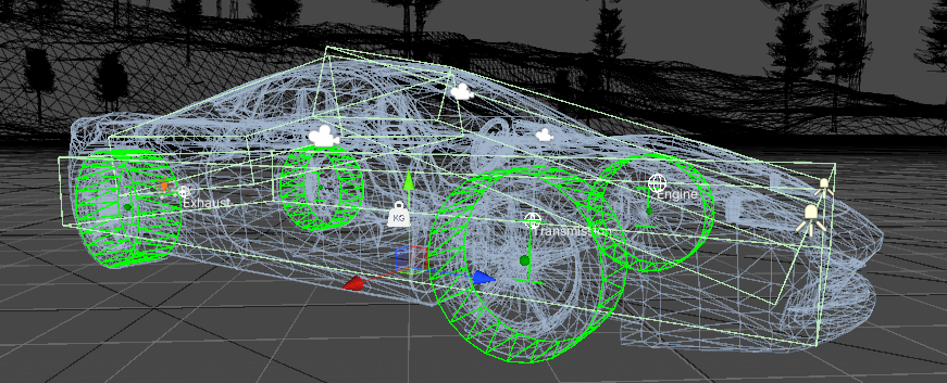
One of the included, fully configured vehicle examples.
Note
This manual describes v14. For an existing vehicle from v13, read the upgrade notes before importing it into v14.
Vehicle components and state
VehicleComponent is a building block of NWH Vehicle Physics 2.
VehicleController is a collection of VehicleComponents, which includes modules, effects and sound components.
Enabled / disabled
A component that is enabled and initialized is updated. Disabled components are not initialized until they get enabled for the first time. Disabling a manager such as SoundManager, EffectManager, ModuleManager or Powertrain also disables its child components.
Each VehicleComponent has a state bar in the inspector. This is where the state of the component can be checked and changed. Changes made in play mode affect runtime values and revert after exiting play mode. The state bar is intended for previewing the current state and testing different values during runtime. For persistent state, use State Settings.
LOD index
LOD allows you to turn off components as the vehicle moves away from the camera. A component with LOD index 1 is available at vehicle LOD 0 and 1, and is disabled at LOD 2 or higher. Set its LOD index to -1 to ignore LODs.
In v14, LOD restores components that it disabled as the camera moves away. A component disabled in State Settings or by a script is not automatically switched on just because it is close to the camera. Likewise, waking a vehicle does not enable every component that was deliberately disabled.
State settings
To prevent having to adjust the states of each component on each vehicle, a StateSettings ScriptableObject is used. Assign it under VehicleController > Settings. Several vehicles can share the same settings, or you can make separate assets for player vehicles and traffic.
Changing state from a script
The following is a fragment for a script that already has a reference to an initialized vehicle component:
myVehicleComponent.state.lodIndex = -1;
myVehicleComponent.VC_Enable(false);
// Later, when the component is no longer needed:
myVehicleComponent.VC_Disable(false);
Pass false for a direct state change from your script. The true argument is used by the parent controller or manager when it enables or disables its children.
All the component initialization and update functions start with the VC_ prefix to prevent confusion with Unity callbacks, e.g. VC_Initialize or VC_FixedUpdate. In v14 the update methods receive delta time. See Scripting and architecture when writing a new component.
Input
Important
For the included demos, use Edit > Project Settings > Player > Other Settings > Active Input Handling > Both. An Input System-only scene can use Input System Package (New), provided nothing in that scene reads the legacy input API.
Input Concept
The input in NWH Vehicle Physics 2 revolves around InputProviders. These scripts obtain user input from different sources such as InputSystem or a custom integration (e.g. keypresses, mouse movement, gamepad input, etc.), process it, and pass it on to the vehicles.
Multiple InputProviders can coexist, allowing for e.g. MobileVehicleInputProvider, InputSystemVehicleInputProvider, and FFBInputProvider to be present simultaneously. Input from active, enabled vehicle providers is combined. Numeric values are added and button values are combined with OR, so two providers reading the same device can double the input.
Input Retrieval
Keyboard / gamepad / touch / steering wheel
                    |
         Vehicle input providers
                    |
          VehicleInputHandler
                    |
         Vehicle's input states

Scene input providers -> cameras, vehicle switching and GUI
The diagram above illustrates the path from the input source to the vehicle input state:
- Input is obtained from hardware through Input Sources. This can be input from any method available in Unity: Input System, Input Manager, touchscreen/sensors, or DirectInput for steering wheel input.
- InputProviders pass this input to the vehicle (
VehicleController.input). Input from all sources is combined and processed based on settings for the specific vehicle. - If
Auto Set Inputis set to true, the state of the corresponding input for the vehicle in question will be set to the combined value of all inputs. - If the VehicleController has
Input > AutoSetInputset to false, the new input will be discarded. Use this when input is set by another script, such as AI or replay. Automatic input also respects vehicle ownership: withVehicleChanger, only the selected vehicle reads player input. Unselected or remote vehicles reset automatic input instead of copying the player controls.
Notes
- A single InputProvider supplies input for all vehicles, so it is recommended to have only one InputProvider of a particular type (e.g., one desktop and one mobile input provider, allowing vehicles to receive both desktop and mobile input simultaneously).
- Input providers only provide input; they do not set it. Vehicles acquire input from input providers if
autoSetInputis enabled on them. - All InputProviders inherit from either
VehicleInputProviderBase(for vehicle-related input) orSceneInputProviderBase(for scene-related input, such as cameras). Thus, it's best to consider InputProviders as a standardized interface between different input methods and a vehicle. InputProviders are divided into VehicleInputProviders and SceneInputProviders. VehicleInputProviders transmit vehicle input (throttle, brakes, etc.), while SceneInputProviders handle scene input (vehicle changing, camera changing, camera movement, and other inputs not directly related to the vehicle). Add a vehicle provider to drive the vehicle, and a scene provider when those scene controls are needed (e.g.,InputSystemVehicleInputProviderandInputSystemSceneInputProvider).- Input is stored inside the
VehicleInputStatesstruct and can be copied from one vehicle to another if needed. For example, this is done when a trailer is connected to a towing vehicle. - To manually set the input states, ensure
autoSetInputis set to false.
Available Bindings
Vehicle Input Provider Bindings
Important
The defaults below are from the shipped Input System action assets. The legacy Input Manager needs its own named bindings; out-of-the-box gamepad bindings are only available for Input System.
| Name | Type | Keyboard Defaults | Gamepad Defaults | Description |
|---|---|---|---|---|
Steering |
axis [-1,1] | A/D | Left Stick - Left/Right | Steering. |
Throttle |
axis [0,1] | W | Right Trigger | Throttle. |
Brakes |
axis [0,1] | S | Left Trigger | Brakes. |
Clutch |
axis [0,1] | Clutch pedal: 0 released (engaged), 1 pressed (disengaged). | ||
Handbrake |
axis [0,1] | Space | B (Xbox) / Circle (PS) | |
EngineStartStop |
Button | E | ||
ShiftUp |
button | R | Right Shoulder | |
ShiftDown |
button | F | Left Shoulder | |
ShiftIntoR1 |
button | Minus (-) | Shift into 1st reverse gear. | |
ShiftInto0 |
button | 0 | Shift into neutral. | |
ShiftInto1 |
button | 1 | Shift into 1st forward gear. | |
ShiftInto[n] |
button | 2,3,4,etc. | Shift into [n]th gear. | |
LowBeamLights |
button | L | Y (Xbox) / Triangle (PS) | |
HighBeamLights |
button | K | ||
HazardLights |
button | J | ||
ExtraLights |
button | ; | ||
LeftBlinker |
button | Z | ||
RightBlinker |
button | X | ||
Horn |
button | H | ||
| Module bindings | ||||
FlipOver |
button | M | Used for FlipOverModule. | |
Boost |
button | Left Shift | A (Xbox) / X (PS) | Used for NOSModule. |
Cruise Control |
button | N | Used for CruiseControlModule. | |
TrailerAttachDetach |
button | T | X (Xbox) / Square (PS) | Used for Trailer and TrailerHitch modules. |
Scene Input Provider Bindings
| Name | Type | Keyboard Defaults | Gamepad Defaults | Description |
|---|---|---|---|---|
ChangeCamera |
button | C | Start | Changes camera. |
CameraRotation |
2D axis | Mouse Delta | Right Stick | Controls camera rotation. |
CameraPanning |
2D axis | Mouse Delta | Right Stick | Controls camera panning. |
CameraRotationModifier |
button | Mouse - LMB | Right Stick Press | Enables camera rotation. |
CameraPanningModifier |
button | Mouse - RMB | Left Stick Press | Enables camera panning. |
CameraZoom |
axis | Mouse - Scroll | D-Pad Up/Down | Camera zoom in/out. |
ChangeVehicle |
button | V | Select | Change vehicle or enter/exit vehicle. |
FPSMovement |
2D axis | WASD | Left Stick | Demo FPS controller movement. |
ToggleGUI |
button | Tab | Toggles demo scene GUI. |
Input Methods
Input Manager (Old/classic)
- Type of
InputProviderfor handling user input on desktop devices through keyboard and mouse or gamepad. - Uses old Unity InputManager. For new projects, it is recommended to use the Unity's new InputSystem instead as InputManager is becoming obsolete.
Note
Since v1.1 InputSystem package is required even if not used. If using the old/classic Unity input set Project Settings => Player => Input Handling to Both and proceed as normal. InputSystem package being present installed will not interfere with old/classic Unity input / InputManager.
Installation
When first importing NWH Vehicle Physics 2 the project will be missing required bindings. There are two ways to add those:
- Manually adding each entry to Project Settings > Input Manager. The provider reads the exact names
Steering,Throttle,Brakes,ClutchandHandbrake; Unity's defaultHorizontalandVerticalaxes are not used. - Backing up the existing file, then copying the axis entries from InputBindings.txt and appending them to the contents of the
[UnityProjectPath]/ProjectSettings/InputManager.assetfile. To do so:- Close Unity.
- Open InputManager.asset in Notepad/Notepad++/Visual Studio or any other text editor of your choice.
- Copy the contents of the provided InputBindings.txt file (
Packages/com.nwh.vehiclephysics/Runtime/VehicleController/Input/InputProviders/InputManager/InputBindings.txt) and paste them at the end of the InputManager.asset. Merge the axis entries into the existingm_Axeslist, preserving the indentation and the project's other bindings; do not paste a second YAML header or a secondm_Axeskey. Save the file. - Open Unity. Check Project Settings => Input. The input bindings for NWH Vehicle Physics will appear towards the bottom of the list.
Scene Setup
To set up InputManager-based input in the scene add the following components to the scene:
- 'InputManagerVehicleInputProvider'
- 'InputManagerSceneInputProvider' Any vehicle that is present in the scene will now receive input from these providers.
Input System (new)
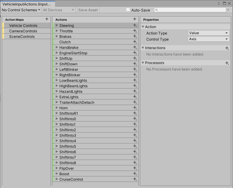
Default InputActions.
- Since v1.1 NWH Vehicle Physics 2 has moved to InputSystem as a default input method.
- v14 requires Unity 6. The Input System package is installed as a package dependency.
Important
If a controller-remapping tool exposes both the original device and a virtual gamepad, check for duplicate input.
Installation
- Install 'Input System' package through Window => Package Manager
- Under Edit => Project Settings => Player => Other Settings =>
Active Input Handling selectInput System Package (New)orBoth- the latter in case your project still usesUnityEngine.Inputsomewhere.
Scene Setup
- Add
InputSystemVehicleInputProviderandInputSystemSceneInputProviderto any object in your scene. - For different controls, use runtime rebinding or a project-owned action asset and provider. The shipped provider constructs its generated action wrapper; editing a copied
.inputactionsfile alone does not change what it reads. Keep project changes outside the package cache.
Rewired and other input packages
The old Rewired integration package is not included in v14. A custom provider can read Rewired or another input source and supply the same vehicle controls. See the custom-provider example below. Use one set of providers for the chosen input method to avoid duplicate input.
Mobile Input Provider
- Add
MobileVehicleInputProviderandMobileSceneInputProviderto the scene. - Create a few UI => Button objects inside your canvas. Make sure that they are clickable.
- Remove the
UnityEngine.UI.Buttoncomponent and replace it withMobileInputButton.MobileInputButtoninherits fromUnityEngine.UI.Buttonand addshasBeenClickedandisPressedfields which are required forMobile Input Provider - Drag the buttons to the corresponding fields in the
MobileVehicleInputProviderandMobileSceneInputProviderinspectors. Empty fields will be ignored.
Steering Wheel Input Provider
v14 uses the DirectInput FFB sample with FFBInputProvider and FFBVehicleSettings. The old Logitech SDK provider is no longer used. Follow DirectInput force feedback setup for the sample prerequisites, device bindings and wheel settings.
Retrieving input from a script
Since multiple providers can be present in the scene, their input has to be combined to get the final input result. To get the combined vehicle input, use the following fragment with NWH.Common.Input and NWH.VehiclePhysics2.Input imported:
float throttle = InputProvider.CombinedInput<VehicleInputProviderBase>(i => i.Throttle());
bool engineStartStop = InputProvider.CombinedInput<VehicleInputProviderBase>(i => i.EngineStartStop());
For the input that a particular vehicle is actually using, read vehicleController.input instead. It includes that vehicle's processing and input modifications.
Manually setting input
Input in each vehicle is stored in myVehicleController.input.states. In case input should not be retrieved from the user but from another script, as is the case when AI is used, autoSetInput should be set to false. This will disable automatic input fetching from the active providers.
Input can now be set from a script that has the vehicle reference:
myVehicleController.input.autoSetInput = false;
myVehicleController.input.Steering = 0.5f;
// Equivalent direct access:
myVehicleController.input.states.steering = 0.5f;
When using input generated by code it is usually handy to have access to a single throttle/brake axis. Vertical = 0.5f sets throttle to 0.5 and resets brakes; Vertical = -0.5f sets brakes to 0.5 and resets throttle. Clear Swap Input In Reverse if your controller treats throttle and brakes as pedal inputs regardless of the selected gear.
The alternative is using inputModifyCallback. It is executed after the input is retrieved by the vehicle and allows modifying the inputs without having to worry about them being overwritten by the same retrieval pass. It also runs when automatic input is disabled. For example, register the following listener once in your script's setup method:
myVehicleController.input.inputModifyCallback.AddListener(MyInputModificationFunction);
The callback, in the same class with access to myVehicleController, can then change the input:
private void MyInputModificationFunction()
{
    myVehicleController.input.Handbrake = 1f;
}
Remove the listener when the script no longer owns the input. The event can also be assigned in the Input inspector.
Custom input provider
If a custom provider is needed it can be written by deriving from VehicleInputProviderBase. Custom providers allow for new input methods or for modifying the existing ones. For example, if the mobile provider does not fit the needs of the project, a copy can be made and modifications done on that copy. That way it will not get overwritten when the asset is updated.
Override the controls you need. Unused methods already return a neutral value; ShiftInto() returns VehicleInputStates.NO_SHIFT when no gear is requested. Scene controls such as camera changes and ToggleGUI() belong in a separate SceneInputProviderBase subclass.
using NWH.VehiclePhysics2.Input;
using UnityEngine;

public class CustomVehicleInputProvider : VehicleInputProviderBase
{
    [Range(0f, 1f)] public float throttle;
    [Range(0f, 1f)] public float brakes;
    [Range(-1f, 1f)] public float steering;

    public override float Throttle() => throttle;
    public override float Brakes() => brakes;
    public override float Steering() => steering;
}
Add this component to a scene object and replace the example fields with input from your device or control system. If the script uses a custom assembly definition, add a reference to NWH.VehiclePhysics2. See assembly definitions for details.
Steering response
Keyboard input usually benefits from the input handler's Steering Smoothing Time and Steering Return Time. For a steering wheel, set both to 0 if direct response is wanted. The vehicle's Steering section can apply further angle limits and assists, so check both places when tuning steering feel.
Powertrain
About
- NWH Vehicle Physics 2 uses a physically accurate solver based on torque and angular velocity.
Powertrainin NWH Vehicle Physics 2 is a collection of Powertrain Components such asEngineComponent,ClutchComponent,DifferentialComponent, etc.
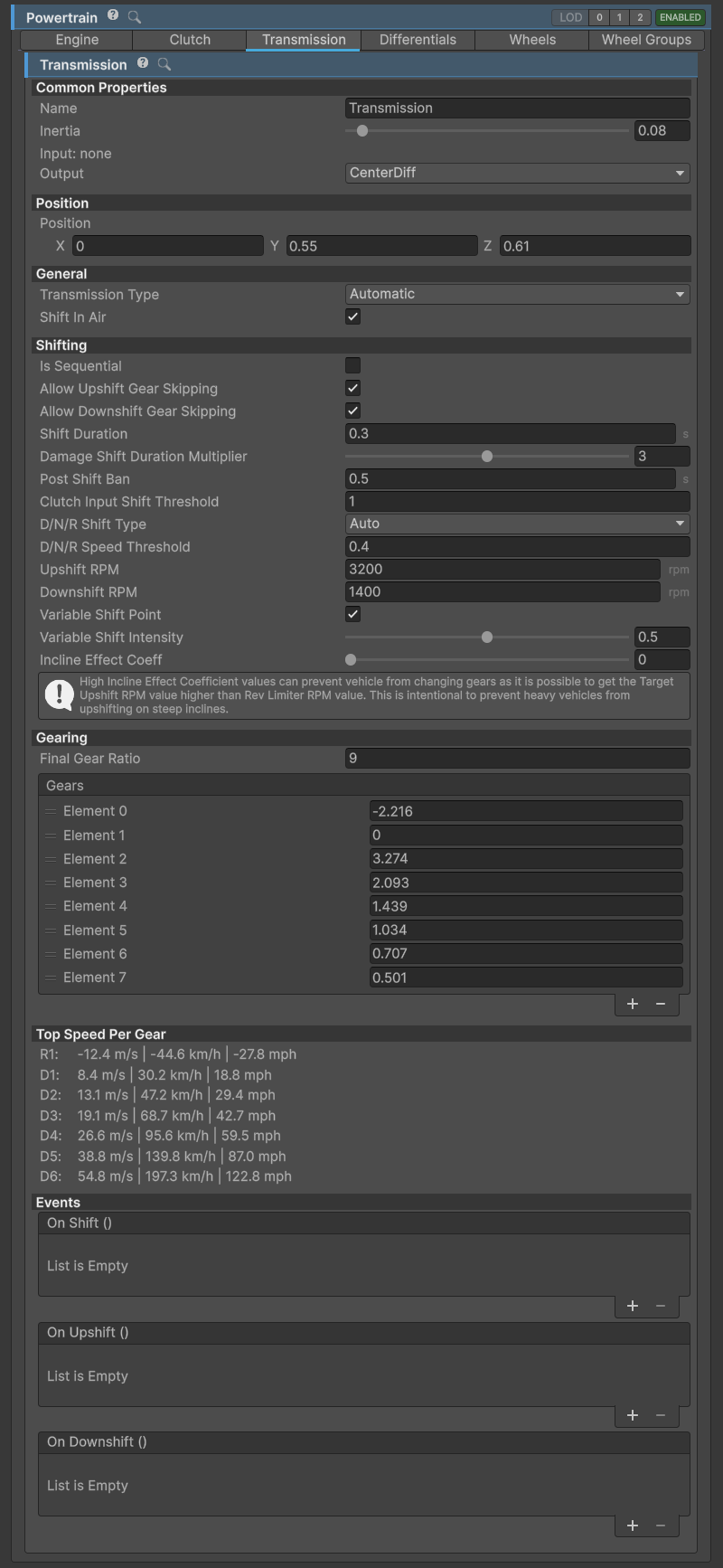
Powertrain menu for filtering between component types.
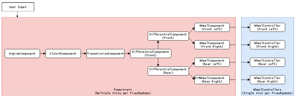
Example of typical Powertrain setup for 4-wheel, 4WD vehicle. In v14, WheelControllerManager coordinates both wheel and powertrain substeps.
- Each component outputs to one or more
PowertrainComponents, except forWheelComponentwhich always outputs toWheelController. EngineComponentwhich acts as a power source andWheel Componentacts as a power sink. The components in-between determine how the power/torque will be transmitted.
Connecting powertrain components
The PowertrainComponent serves as a foundational class for all powertrain components, including EngineComponent, ClutchComponent, TransmissionComponent, and others.
Each PowertrainComponent possesses the following shared attributes in the Inspector:
Name- The label assigned to the component. Note that altering theNameof a component will reset theOutputfor any components that utilize that component.Inertia- Represents the inertia of the component. The inertia of each component contributes to the overall system inertia, which determines the difficulty of spinning the component up or down.Output- Specifies thePowertrain Componentto which torque is forwarded. For certain components, such asDifferential Component, multiple outputs may be present (e.g., left and right wheel).
The Engine inspector below shows these fields under Common Properties.
Keep in mind the following:
- Modifying the
namefield of a component resets all theOutputs for otherPowertrainComponents that rely on that component as an output. - Increasing the
Inertiavalue will cause the component to spin up more slowly when the same amount of torque is applied. - The
Inertiaof aWheelComponentis determined by theWheelControllers mass and radius settings.
Important
Always ensure that the Inertia value is greater than 0!
Engine
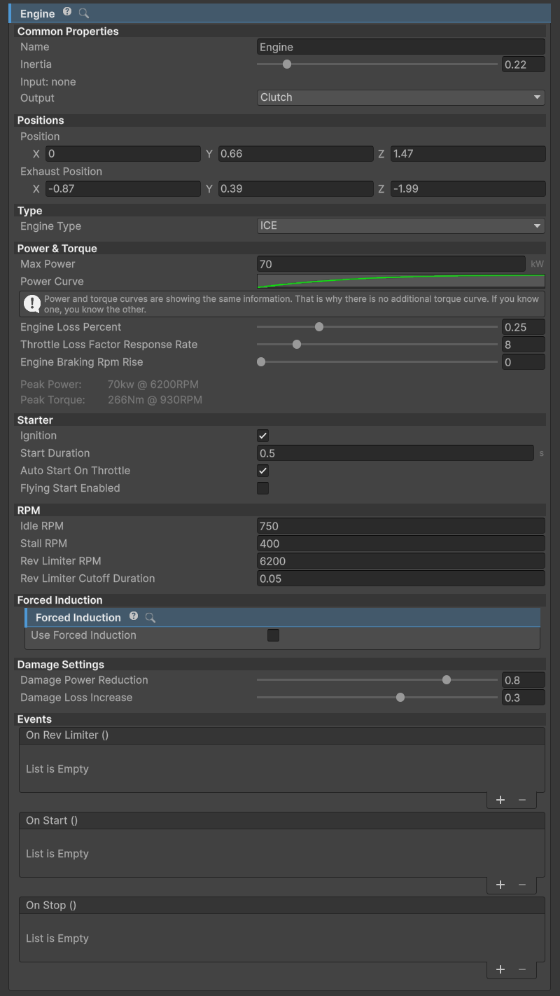
EngineComponent inspector.
The engine acts as a source of power/torque and updates the components attached to it recursively with the generated torque.
Note
When using the Electric engine, consider setting the output to the Transmission, bypassing the Clutch, as it is not needed.
Inertia
Higher engine inertia results in an engine that is harder to stall. Such an engine will also take longer to spin up. Typical values:
- Sports car: 0.2
- Average car: 0.3-0.5
- Semi truck: 1-1.5
Power Curve
The power curve represents engine power across its RPM range.
X and Y values are normalized where X (0 to 1) represents RPM as a percentage of Rev Limiter RPM and Y (0 to 1) represents power as a percentage of Max Power.
Note
Note that power and torque curves show the exact same data since the power is a function of torque and RPM, so knowing two of the three is enough. Since power curves are usually easier to find, NVP2 uses a power curve instead of a torque curve.
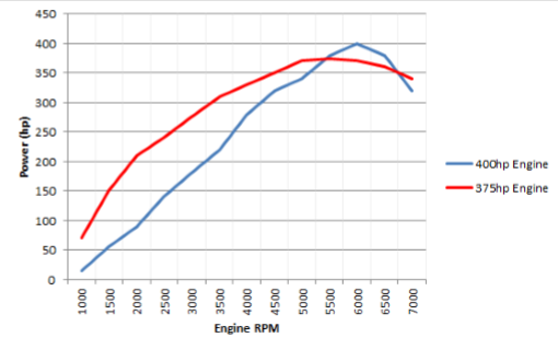
Similar power output, different power curves.
Idler Circuit
The Idler circuit tries to keep RPM at Idle RPM when there is no user input. In v14 a PID governor modulates the throttle to hold idle under load. It is still possible to stall an ICE engine below Stall RPM. Keep Idle RPM comfortably above Stall RPM; set Stall RPM to 0 to disable stalling.
Starter
Starter spins up the engine to try and reach the RPM at which the power generated by the engine is enough for it to spin by itself and overcome the losses. The amount of torque needed is automatically calculated based on the engine inertia, Power Curve, and the Start Duration value.
When Flying Start is enabled, the engine spins up instantly without running the starter. This is to give an illusion of the engine already having been started when the vehicle is woken up.
Rev Limiter
Cuts throttle to the engine when RPM reaches Rev Limiter RPM for a duration of Rev Limiter Cutoff Duration.
Engine losses
Max Power is specified in kW. Engine Loss Percent controls the losses that oppose rotation, so it also affects engine braking when the throttle is released. Tune the power curve and losses together before changing the gearing to compensate for an engine that has too little torque.
Electric motors do not use the starter, idle governor or forced induction. Select the engine type before entering play mode.
Power modifiers
Power modifiers can be used through scripting to modify the power of the engine. These are functions that return a float which denotes an engine power coefficient. In v14 each callback receives delta time. For example, in a class that provides boostIsActive:
public float AddBoost(float deltaTime)
{
    return boostIsActive ? 1.5f : 1f;
}
Register it once with myVehicleController.powertrain.engine.powerModifiers.Add(AddBoost) and remove it when the owning script no longer needs it. This is a fictional example. A concrete example can be found inside the TCS module which uses this mechanic to limit power when there is wheel spin.
Forced induction
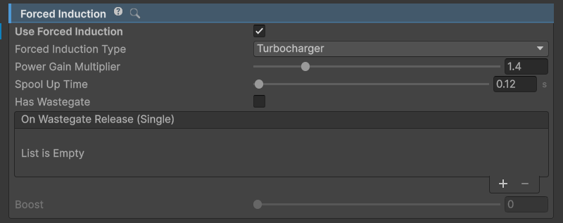
Forced Induction inspector.
ForcedInductionis a part ofEngineComponent. It can be used for both turbocharging and supercharging the vehicle.Power Gain Multiplieradds power on top of the existingMax Powerso the vehicle with 100kW andPower Gain Multiplierof 1.5 can produce 150kW at full boost.- Boost value affects sound components
ForcedInductionComponentandTurboFlutterComponent. If forced induction is to be used just for the sound effectsPower Gain Multipliershould be set to 1.
Select Turbocharger for boost that builds with exhaust flow and has a spool delay. Supercharger follows engine RPM without that delay. Spool Up Time controls how quickly a turbo builds boost. Enable Has Wastegate for the release event used by the turbo flutter sound.
Clutch
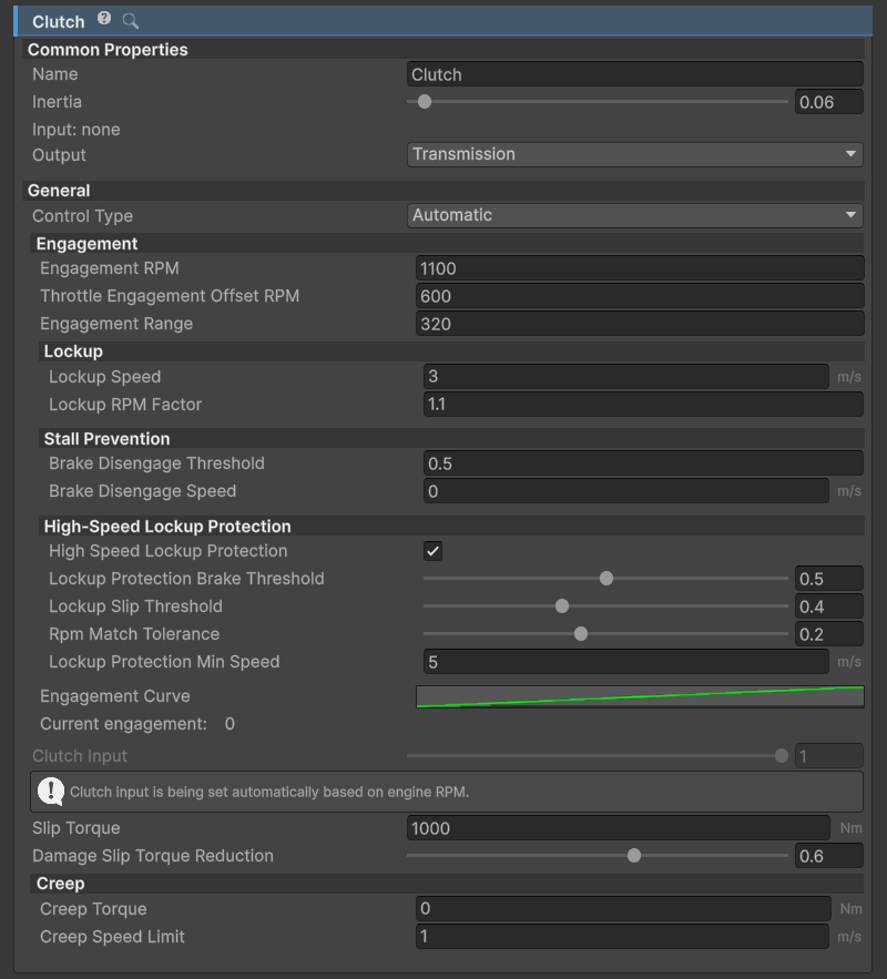
ClutchComponent inspector.
ClutchComponent can be bypassed by setting the output of EngineComponent directly to the desired PowertrainComponent but this is not recommended as it will cause stalling in most cases.
Clutch Control
There are two things to note here: clutch engagement and clutch input. Clutch input controls the engagement through the Engagement Curve and is set either automatically, through user input, or scripting/inspector. Engagement describes how far the clutch has reached its "biting point". In v14 the player input is pedal travel: 0 means released and engaged; 1 means pressed and disengaged. The internal clutchInput field goes the other way: 0 means disengaged and 1 means engaged.
Automaticsets the clutch engagement based on the input (engine) RPM.- During launch, engagement starts at
engagementRPM + throttleEngagementOffsetRPM * throttle²and rises acrossengagementRange. A wider range gives a more gradual engagement. The automatic clutch also reduces engagement near a stall and during low-speed braking.
- During launch, engagement starts at
UserInputtype can be used to give control to the user through a gamepad, steering wheel, etc.- When this control type is selected, the clutch is controlled through the
Clutchaxis - check Input section for more info on setting up axes.
- When this control type is selected, the clutch is controlled through the
Manualtype does not set the clutch value in any way and instead expects to be set externally, either through the inspector or through scripting.
Slip Torque
Slip Torque is the maximum torque the clutch can transmit when fully engaged. v14 uses the same clutch capacity for all transmission types; the old torque-converter switch is no longer present.
Slip torque for an average clutch should be slightly higher than the maximum engine torque—usually a few hundred to a few thousand Nm.
Too high
Slip Torquewill result in grabby clutch.Using too high
Slip Torquevalues can result in torque spikes when the clutch is suddenly released which can impact solver stability in extreme cases.Values near zero will result in the engine spinning up as if the clutch is not engaged due to clutch slip.
Creep
- Some automatic transmissions have slight creep when engaged in D or R. This is normally caused by the torque converter (which is essentially a type of clutch) and it allows some of the torque from the engine to escape to the wheels.
In v14, Creep Torque supplies a low-speed torque floor which fades out at Creep Speed Limit. It remains limited by clutch engagement and Slip Torque: a completely open clutch cannot transmit creep. Set Creep Torque to 0 if creep is not wanted.
Lockup and braking
The automatic clutch blends toward full engagement above Lockup Speed, provided the engine has enough RPM. High Speed Lockup Protection backs off engagement if hard braking locks the driven wheels, helping prevent an engine stall. Adjust Lockup Slip Threshold if that intervention happens too early or too late.
If the engine stalls as the vehicle comes to a stop, check the automatic clutch's engagement RPM and brake-disengagement settings before increasing engine inertia. If the clutch feels grabby, widen Engagement Range or lower an excessive Slip Torque.
Transmission
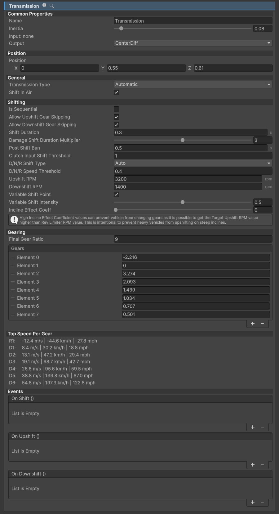
TransmissionComponent inspector.
TransmissionComponentis a mandatoryPowertraincomponent. It is always third in thePowertrain.Componentslist.NWH Vehicle Physics uses gear ratios – just like the real transmission does.
If gears are not set up properly the vehicle will not move.
Input Flipping
The asset uses W/S to select the movement direction by default. To use W/S as throttle/brake exclusively go to Control > Input and clear Swap Input In Reverse. With this setting enabled, throttle and brake swap roles in reverse gear; with it disabled, W remains throttle and S remains brake in either direction.
Gearing
- Gearing is assigned through the
gearslist and should be ordered from reverse, then neutral (always 0), then forward gear ratios. - Gear ratios can be adjusted during runtime.
For example, -4, 0, 6, 4, 3, 2 gives one reverse gear, neutral and four forward gears. With several reverse gears, R1 is the negative entry next to neutral; list the taller reverse ratios first. Final Gear Ratio multiplies all the ratios. Increasing it gives more torque at the wheels at the cost of road speed for a given engine RPM.
Transmission Types
Manual
- In this type of transmission changing gears can only be done through user input. Check Input Setup for more info on input bindings.
Automatic
- Vehicle shifts gears based on the gear ratios and
Upshift RPM,Downshift RPM,Variable Shift IntensityandIncline Effect Coeffvariables. - Current
Target Upshift RPMandTarget Downshift RPMcan be seen under the Shifting section of theTransmissionComponentinspector, during runtime. These values vary depending on the variables mentioned above. IsSequentialmakes the transmission be able to shift only one gear up or down at the time. It prevents gear skipping. WithIs Sequentialdisabled,Allow Upshift Gear SkippingandAllow Downshift Gear Skippinglet the transmission skip intermediate gears in the corresponding direction.
Compare Target Upshift RPM and Target Downshift RPM at full throttle and with the throttle released to see how load changes the shift points.
CVT
CVT(and eCVT) transmissions have variable gearing ratio dependent on load.- Use one reverse ratio, neutral and one forward ratio in the
Gearslist.CVT Target RPM Percentsets the engine speed it tries to hold, as a fraction of the rev limiter RPM.CVT Response Ratecontrols how quickly the ratio changes.
External
shiftDelegateinsideTransmissionComponentis used for changing gears. Its v14 signature receives the vehicle and delta time.- This allows for external shifting logic.
- If the delegate is not assigned this option will result in no gear shifts.
Timing
To make shifting more realistic two timers have been added:
Shift Duration- timeTransmissiontakes to change from one gear to another. During this timeEngineComponent's throttle is cut off. Works for all transmission types.Post Shift Bantimer. This field determines minimum time between two shifts. Used to prevent transmission for shifting too often. Only affects automatic transmission types.
Shift conditions
Shift In Air controls whether the transmission can shift when all wheels are off the ground. It is not a check that every wheel must be grounded. The old wheel-spin, wheel-skid and external shift-check checklist is no longer used in v14.
For a manual clutch, Clutch Input Shift Threshold sets the maximum engagement allowed for a gear change. Set it to 1 if shifts should be allowed without pressing the clutch. With an H-pattern shifter, enable Hold To Keep In Gear if releasing the gear input should select neutral.
For automatic D/N/R selection, choose whether the direction changes automatically or requires shift input under Automatic Transmission DNR Shift Type. DNR Speed Threshold limits these changes to low speed.
Transmission gearing profile
Transmission gearing profiles were deprecated in favor of a simple gears list. Existing v13 gear data needs attention during migration; see the v14 upgrade notes.
Differentials
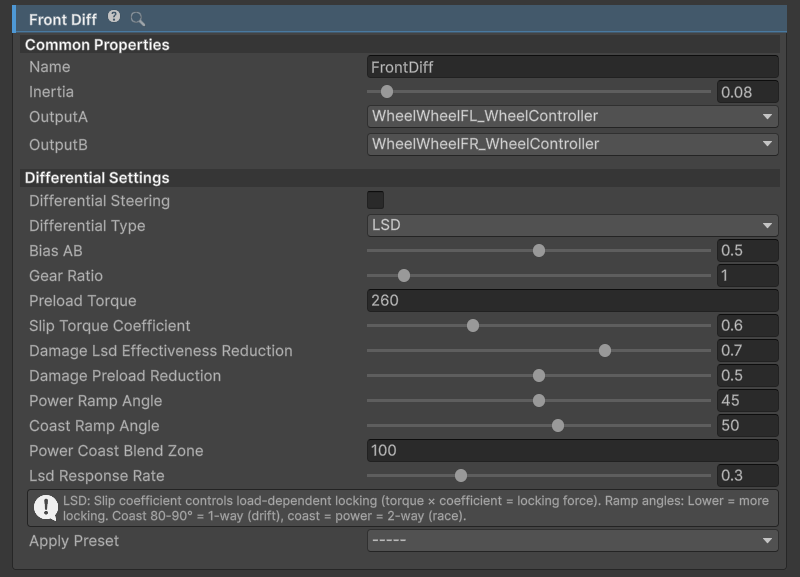
DifferentialComponent inspector.
DifferentialComponent is a type of PowertrainComponent that splits input torque between two outputs.
There can be multiple DifferentialComponents present on one vehicle and one differential can output to other differentials which is useful for 4WD setup with center differential.
Important
Unused differentials should be removed. E.g. a front differential that none of the other powertrain components (transmission, other differentials, etc.) are outputting to should be removed, as only powertrain components that have a path to Engine are updated.
Differential types
Open
Torque in an open differential is equally split between the left output and right output when Bias AB is 0.5. The outputs can turn at different speeds, allowing the outside wheel to travel farther in a corner. An open differential can also let one wheel spin when it has little grip.
Locked
A locked differential keeps both outputs rotating at the same angular velocity. This can be useful off-road, but in a tight turn the tires must scrub to make up the difference in distance travelled. Start with the default lock settings; increase Locked Stiffness only if the lock is too soft. Large values from older tuning examples are not needed by the current solver.
Limited slip
The v14 LSD uses preload and separate power and coast ramp angles. Preload Torque gives the base locking torque, while Slip Torque Coefficient adds locking under load. Lower ramp angles give stronger locking. Power Ramp Angle applies under acceleration and Coast Ramp Angle under engine braking.
Equal power and coast angles give a two-way setup. A higher coast angle gives less locking when lifting off; an angle near 90 degrees leaves very little coast locking. Start with moderate preload and change one setting at a time while comparing corner entry and exit. The old single Slip Torque setting is no longer used.
Torsen
Torsen is the torque-sensing option. Torque Bias Ratio limits how much torque can be biased between outputs. A ratio of 3 allows a 3:1 split. It is useful where a progressive torque bias is wanted without a fully locked axle.
Bias and differential steering
Bias AB is the base split: 0 sends torque to output A, 1 to output B and 0.5 splits it evenly. Gear Ratio normally stays at 1; it provides an additional ratio when the outputs need different gearing. For tracked vehicles, Differential Steering varies the left/right torque distribution with steering input. Steering Range limits that variation.
Configurations: 4WD / 2WD / etc.
To achieve a specific drivetrain configuration, different differential layouts can be used. For example:
- RWD: Set the Transmission output to a Differential whose outputs are rear wheels.
- FWD: Same as RWD, but with the Transmission outputting to a Differential whose outputs are front wheels. Remove any unused differentials.
- AWD/4WD: Can be achieved through three differentials; front, rear and center. The center differential should output to front and rear differentials, which then output to front and rear wheels, respectively.
- Adjustable: A configuration of differentials as in the AWD setup can be used, but with the center differential set to Open type. Adjusting the BiasAB slider on the center differential to 0 will make the car FWD and adjusting it to 1 will make it RWD, assuming the first output of the center differential is the front differential.
- 8x8 and similar: A tree of differentials can be built, which allows for setups such as 6x6, 8x8, etc. Example:
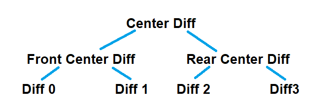
8x8 differential setup example.
Wheels
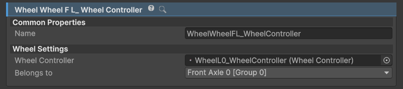
WheelComponent inspector.
WheelComponentis aPowertrainComponent. It acts as a torque sink and can not output to anotherPowertrainComponentWheelComponentshould not be mixed up withWheelControllerorWheelCollider.WheelComponentinstead interfaces between the powertrain and the wheel.Belongs Tofield determines to which WheelGroup theWheelComponentbelongs to. This determines values such as braking, steering and geometry.Inertiafield gets auto-calculated from assignedWheelController's mass and radius.- In v14, assign the actual
WheelControllerto theWheel Controllerfield. Unity's WheelCollider is not supported as a drop-in wheel backend.
The wheel's radius, width, mass, suspension and friction are configured on WheelController and its companion components. StandardFriction contains the friction settings; StandardGroundDetection performs the wheel contact queries. The vehicle's ground-detection system selects the surface preset to use at that contact.
Wheel and powertrain substeps are coordinated by WheelControllerManager, which is created automatically. A WheelControllerGroup contains the wheels belonging to one Rigidbody; it is separate from the wheel groups below, which set axle steering and braking. See the Wheel Controller manual for suspension, tire friction, anti-roll bars and substep tuning.
Wheel groups
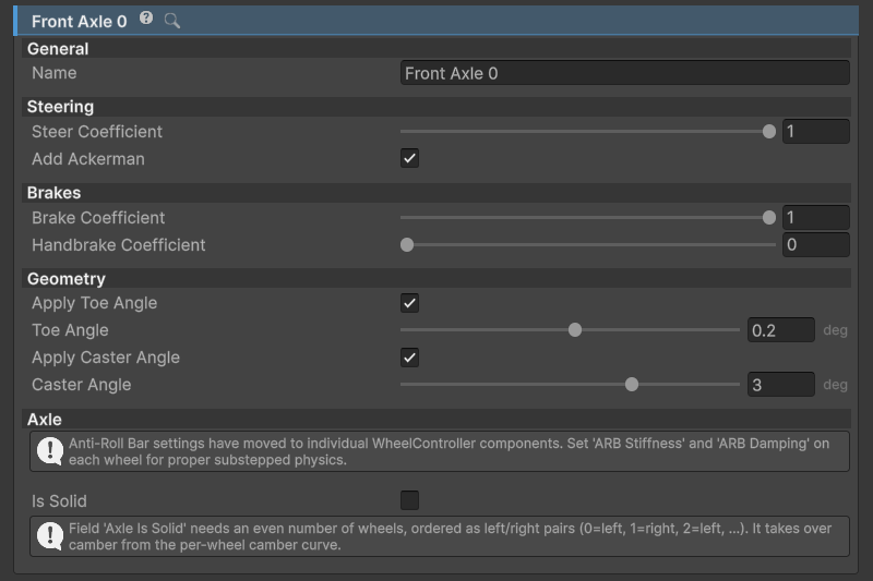
WheelGroup inspector.
Steering
Steer Coefficientdetermines how much the wheel will steer depending on input. In general cars would haveSteer Coefficientof 1 in front and 0 in the back, except for four wheel steering cars where rear axle usually steers opposite of the front so the value would be negative. Examples:1- 100% steering.0- no steering.-0.5- 50% steering in the opposite direction.
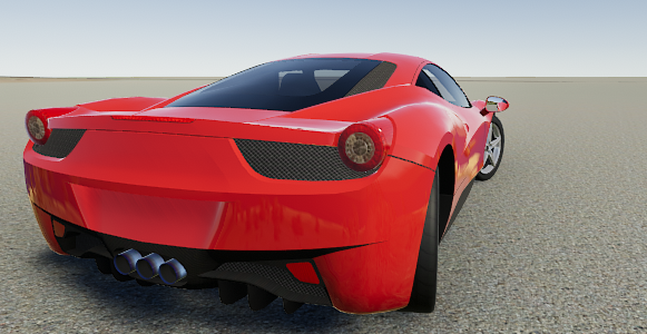
Vehicle with Steer Coefficient of 1 on the front axle and -0.5 on the rear axle. Steering wheel turned fully to the right.
Add Ackerman enables Ackermann steering for wheel pairs. The inside wheel turns farther than the outside wheel, so both can follow their paths around the same turn. v14 calculates the angles from track width and wheelbase; this is a checkbox, not the percentage adjustment shown in older inspectors. It is not used for a single-wheel motorcycle axle.
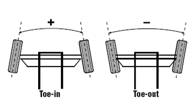
Brakes
Brake Coefficient- amount of brake torque used as a percentage ofBrakes=>Max Torque.Handbrake Coefficient- amount of brake torque applied when handbrake is activated.
Geometry
Toe, caster and camber are set on the WheelControllers. Enable Apply Toe Angle and Apply Caster Angle on the group if those wheel geometry settings should be applied by the vehicle.
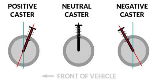
For fixed camber, set the wheel's Camber value. For camber that changes with suspension travel, enable and tune the wheel's Camber Curve.
Solid axles and anti-roll bars
Is Solid imitates a solid axle and auto-adjusts camber so the wheels stay parallel to each other. It takes over camber from the per-wheel curve while enabled. Keep the wheel list in left/right pairs; each pair forms an axle.
In v14, use the WheelController's ARB Stiffness and ARB Damping for an anti-roll bar. The old advice to raise the force application point as a substitute is no longer the intended setup. Start with the suspension working correctly, then tune the anti-roll bar to control body roll.
Sound
About
Sound system in NVP2 consists of SoundManager and multiple SoundComponents. Disabling SoundManager also disables all the SoundComponents.
SoundComponentandSoundManagerareVehicleComponents. Check VehicleComponent page for more info.- Each
SoundComponent(type ofVehicle Component) is responsible for one sound, e.g.EngineRunningComponentorEngineStartStopComponent. AudioSources are not added manually but are instead generated by the script when the scene is started. SomeSoundComponents can have more than oneAudioSource- e.g. wheel relatedSoundComponents have oneAudioSourcefor each wheel.- Each field affects only the vehicle to which the script is attached. To modify the audio output for all the vehicles VehicleAudioMixer (
VehicleAudioMixer.mixer) can be used.
Requirements
Mixerfield must haveAudioMixerassigned. By defaultVehicleAudioMixerwill be used.
Setting up a sound
SoundComponent inherits from VehicleComponent.
Check VehicleComponent page for more info.
Assign the clips and adjust volume and pitch in the sound's inspector. Looping sounds such as the horn use a sustained clip, while events such as a crash or gear change can choose between several clips to reduce repetition. You do not need to add AudioSources by hand.
Engine running sound uses an RPM sample list in v14, as described below. Tire sounds take their clips and settings from the active surface preset.
Sound manager
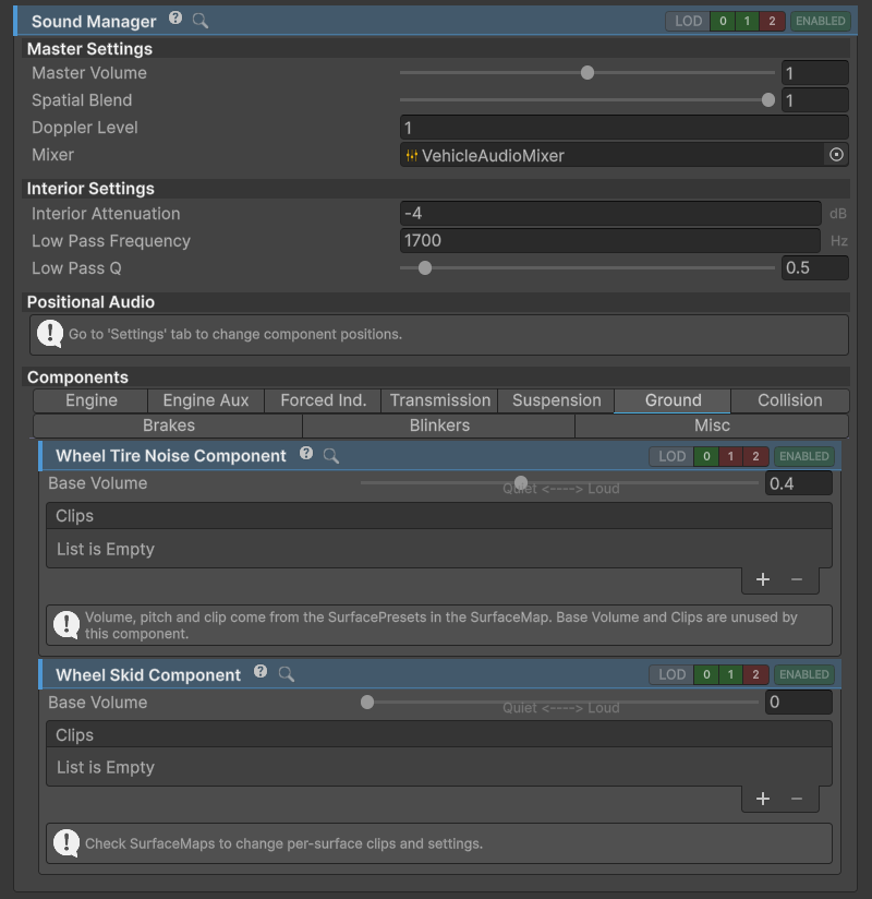
SoundManager inspector.
SoundManager is the main class for handling sound. It contains all the global sound settings and also manages individual SoundComponents.
Also check the Sound page.
Master Settings
Master settings affect all the sound components on this vehicle. Master Volume adjusts their overall level. Spatial Blend controls the balance between 2D and positional sound, while Doppler Level controls the pitch change as the vehicle passes the listener.
For an interior camera, use CameraInsideVehicle and tune Interior Attenuation and Low Pass Frequency to muffle the outside sound. The camera setup is covered under NWH Common Scripts.
Equalizer
Each sound component belongs to one of the Audio Mixer groups: Engine, Transmission, SurfaceNoise, Turbo, Suspension, Crash or Other. Here you can add additional effects and modify the sound. Use the mixer for shared routing and effects. In v14, the engine's load-dependent low-pass, distortion and gain are applied to each vehicle's own sources, so one engine does not change another vehicle's sound.
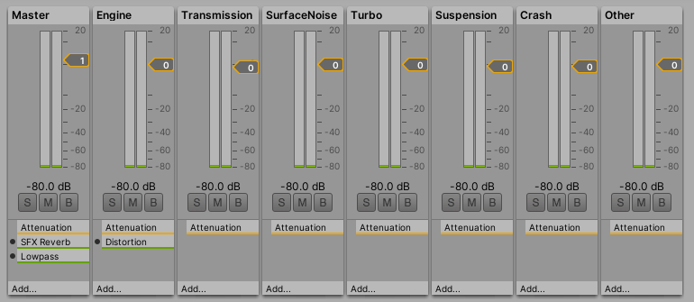
VehicleAudioMixer
Blinkers
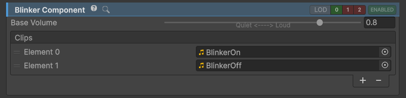
BlinkerComponent inspector.
- Click-clack of the working blinker.
- Accepts two clips, first is for the blinker turning on and the second is for blinker turning off.
Air brakes
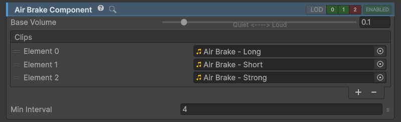
AirBrakeComponent inspector.
- Imitates brake hiss on vehicles with pneumatic brake systems such as trucks and buses.
Crashes
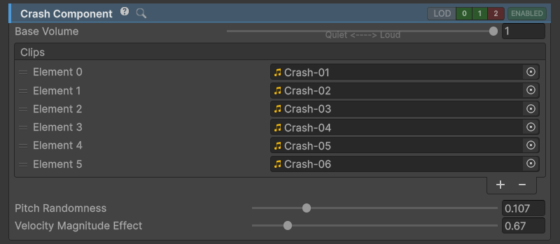
CrashComponent inspector.
- Sound of vehicle crashing.
- Supports multiple audio clips of which one will be chosen at random each time this effect is played.
- Volume is dependent on collision intensity. This can be adjusted through
Velocity Magnitude Effect. - Pitch is random. Randomness can be adjusted through
Pitch Randomnessfield.
Engine fan
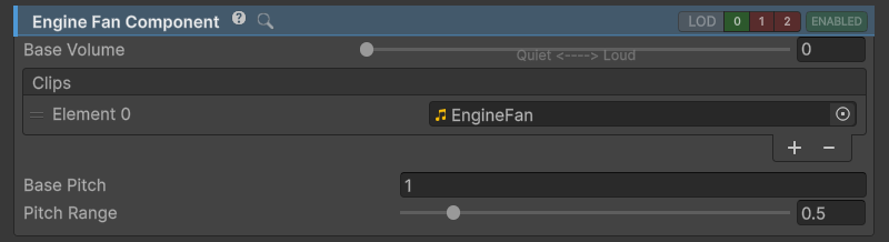
EngineFanComponent inspector.
EngineFanComponent is used to imitate engine fan running, the sound especially prominent in commercial vehicles and off-road vehicles with clutch driven fan.
AudioSourceofEngineFanComponentis positioned at Powertrain > Engine > Position.
Engine running
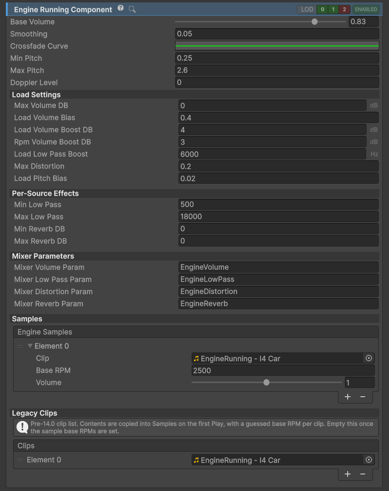
EngineRunningComponent inspector.
EngineRunningComponent is the sound component responsible for the engine sound. In v14 it crossfades recordings made at different RPMs and adjusts their pitch as the engine speed changes.
Add recordings to Engine Samples and enter the RPM at which each clip was recorded in Base RPM. Adjust the volume of each sample so neighbouring recordings blend without an obvious jump. A single sample can still be used when that is all you have, but it must cover a wider pitch range. More recordings let the sound change across the rev range without stretching one clip as far.
Crossfade Curve controls the overlap between samples. Min Pitch and Max Pitch limit how far each recording can be pitched, while Smoothing softens rapid RPM and load changes. Listen through a full acceleration and lift-off, rather than tuning only at idle.
The engine sources are created automatically at the exhaust position. Load changes their volume, low-pass filtering and distortion. Distortion affects volume, so when high levels of distortion are used it is usually a good idea to reduce volume proportionately.
Legacy clips are converted to samples when no usable sample list exists. The assigned base RPMs are estimates: check them against the recordings and save the corrected setup before relying on it.
Engine starting and stopping
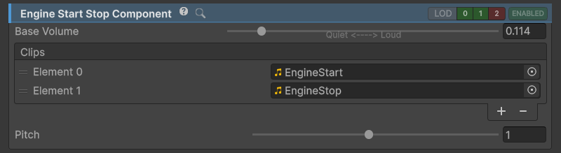
EngineStartStopComponent inspector.
EngineStartStopComponentplays while the starter is active.- First sound clip in the list will be used for engine starting sound.
- If the second clip is added to the list it will be played after the engine stops as an engine stopping sound.
- Starter settings can be adjusted under Powertrain => Engine tab.
AudioSourceofEngineStartStopComponentis positioned at Powertrain > Engine > Position.
Exhaust pops
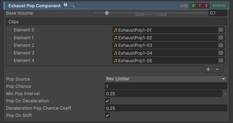
Adds exhaust pops to the vehicle.
Gear changes
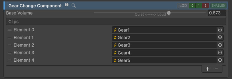
GearChangeComponent inspector.
Sound of changing gears.
- Supports multiple audio clips of which one is chosen at random each time the effect is played.
- AudioSource of
GearChangeComponentis positioned at Powertrain > Transmission > Position.
Horn
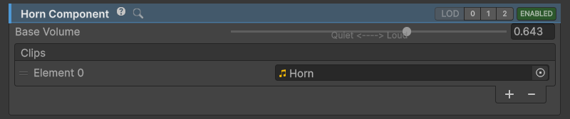
HornComponent inspector.
- Vehicle horn sound.
Reverse beep
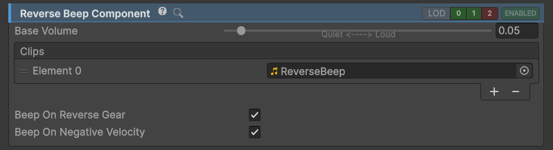
ReverseBeepComponent inspector.
- Beeping sound commercial vehicles make when driving in reverse.
Suspension bumps
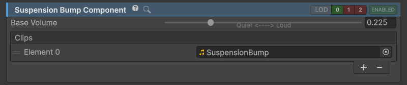
Sound of tire going over obstacle.
Each time the clip is played volume and pitch are changed to reduce repetitiveness. Multiple clips can also be used for the same reason.
Transmission whine
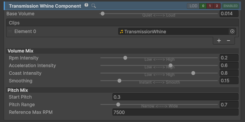
TransmissionWhineComponent inspector.
Sound of vehicle transmission. Most prominent on rally and racing cars with straight cut gears in the gearbox.
AudioSourceofTransmissionWhineComponentis positioned at Powertrain > Transmission > Position.
Turbo flutter
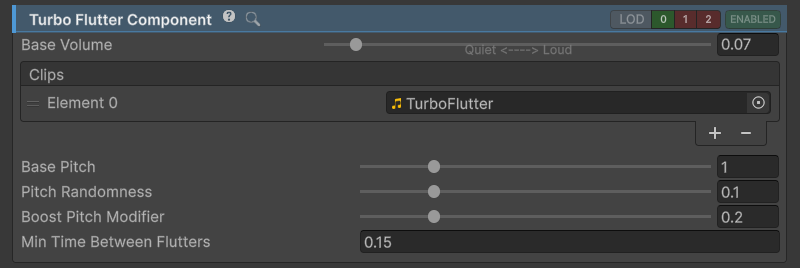
TurboFlutterComponent inspector.
Sound of boost being released on turbocharged vehicles. It is triggered by the forced-induction release event.
- Gets triggered after releasing throttle if there is adequate boost build up in ForcedInduction.
AudioSourceofTurboFlutterComponentis positioned at Powertrain > Engine > Position.
Forced induction sound
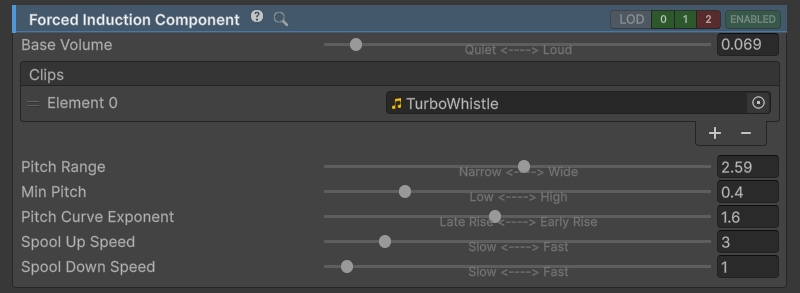
ForcedInductionComponent inspector.
Imitates high-pitched sound of forced induction.
- Can be used for both turbocharger and supercharger sound.
- Sound depends on EngineComponent.ForcedInduction.
AudioSourceofForcedInductionComponentis positioned at Powertrain > Engine > Position.
Tire skid sound
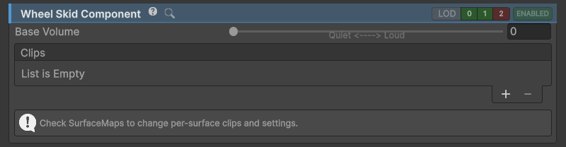
WheelSkidComponentInspector
- Sound produced by slipping/skidding over a surface.
WheelSkidComponentgets clips, volume and pitch settings from activeSurfacePreset.- An
AudioSourcegets generated for eachWheelComponent.
Tire rolling sound
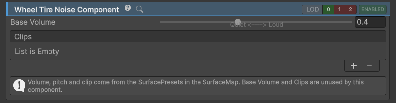
WheelTireNoiseComponent
- Sound produced by tire rolling over a surface.
WheelTireNoiseComponentgets clips, volume and pitch settings from activeSurfacePreset.- An
AudioSourcegets generated for eachWheelComponent.
Effects
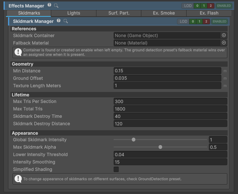
EffectsManager menu.
Controls all the vehicle effects.
Effect system makes use of VehicleComponents and therefore each Effect can be turned on or off, be enabled or disabled or have LOD set.
- All
Effects with manager in the name manage multiple instances of the effect, usually one for each wheel - e.g. skidmarks or surface particles.
Exhaust flash
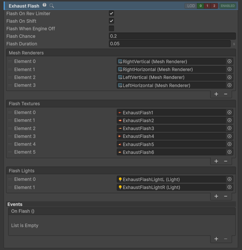
ExhaustFlash inspector.
ExhaustFlash Effect is used to imitate flames shooting out of exhaust. The method to achieve this is identical to the one used for most muzzle flash in FPS games; that is a set of images gets enabled and disabled at rapid rate with different sprite and scale each time. This is a performant way to achieve the effect while avoiding particle effects.
Setup
Adding Quads
- Create and place two
Quads perpendicular to each other. Move them to the location of the exhaust. - Remove any colliders from
Quads. - Create a new material that uses a transparent particle shader compatible with the project's render pipeline. For the default URP project, use the included exhaust-flash material as a starting point. The included example on Sports Car prefab can be copied. Assigning one of the included flame textures will show if the rotation of the
Quadis correct. RotateQuadif needed.
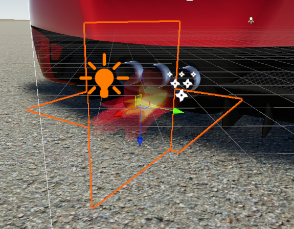
Two perpendicular quads with flame sprites.
- Assign the
MeshRenderers from the newly created Quads to theExhaustFlash=>Mesh Rendererslist.
Assigning Textures
To make flames look more convincing a random texture is assigned to each Quad on each flash. A number of default textures is included.
- Assign textures to
Flash Textureslist.
Adding Point Lights
If the material used for exhaust flash is not emissive, additional PointLight(s) can be added to light the surrounding area on flash.
- Set up a
PointLightand place it at the exhaust location. - After configuring, disable the light.
- Add the light to the
Flash Lightslist.
Exhaust smoke
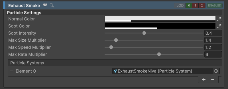
ExhaustSmoke inspector.
ExhaustSmoke controls exhaust ParticleSystem color, size and emission speed. It interpolates between NormalColor and SootColor based on engine state.
Setup
- Position
ParticleSystems at vehicle exhaust position. Prefab of pre-configuredParticleSystemcomes with the asset (search the package and imported Base Sample for the exhaust particle prefab). - Assign the
ParticleSystems to theParticle Systemslist insideExhaustSmokeinspector.
Lights
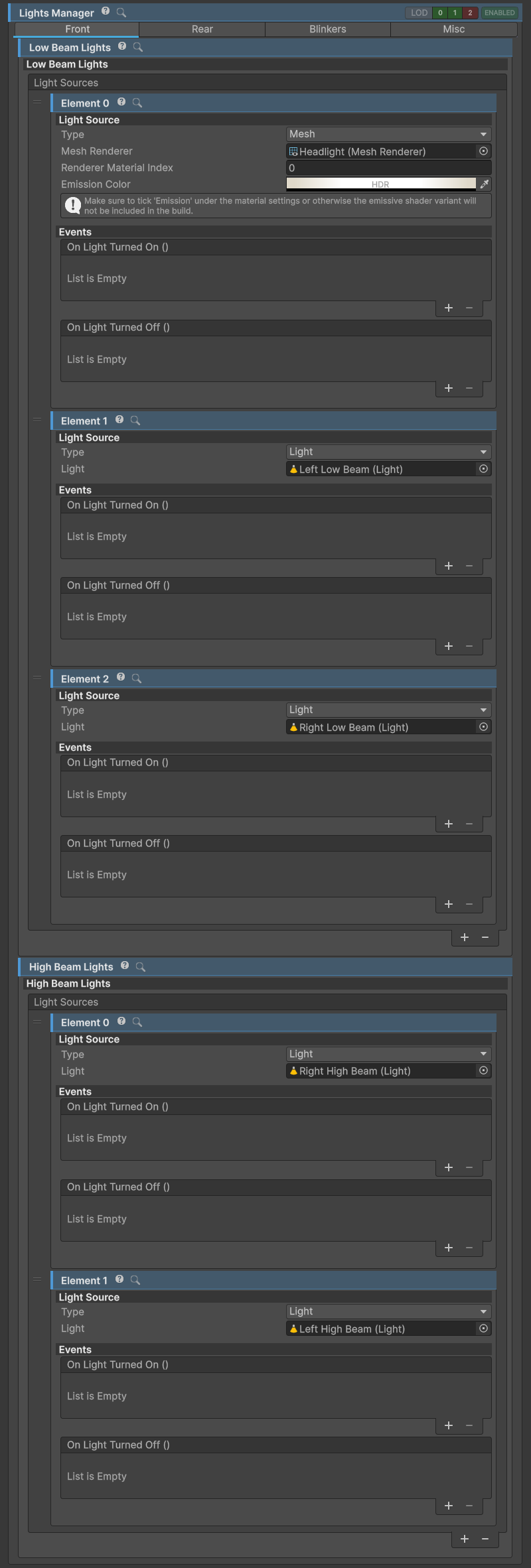
LightsManager inspector.
LightsManager is tasked with turning VehicleLights on or off depending on user input.
Vehicle lights
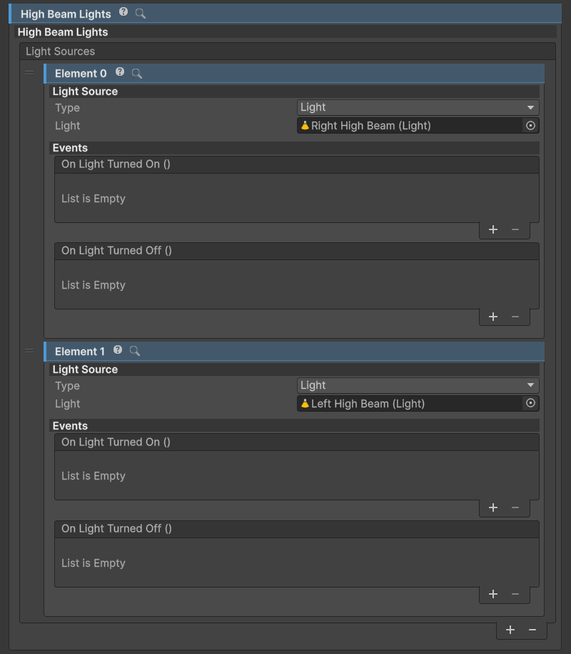
VehicleLight inspector.
VehicleLight is a collection of LightSources. When the light is turned on all LightSources are turned on and vice versa.
Light sources
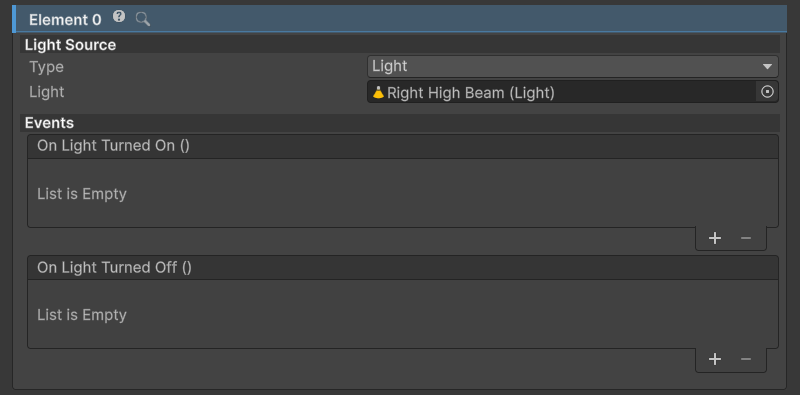
LightSource with Light option selected.
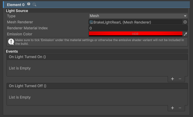
LightSource with Mesh option selected.
One vehicle light source. Can be a Light or emissive Mesh.
- If
Lightis selected asTypeany UnityLightcan be assigned. It will be turned on and off according to user input. - If
Meshis selected asTypea mesh using a material with an_EmissionColorproperty, such as URP/Lit, can be used. Its emission will be toggled to imitate a working light. Since this does not emit enough light to be a headlight usually another light source is used in tandem, this one withSpotLightassigned.
Note
For an emissive mesh light to work it needs to be a separate object. If the model does not come with lights and blinkers as separate objects these will need to be separated in 3D modelling software such as Blender (free, open source).
Important
When using Mesh light source make sure to tick the Emission checkbox on the material. This lets Unity know that this variant of the material is in use and should be included in the build.
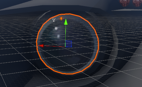
Mesh with Emission turned off.
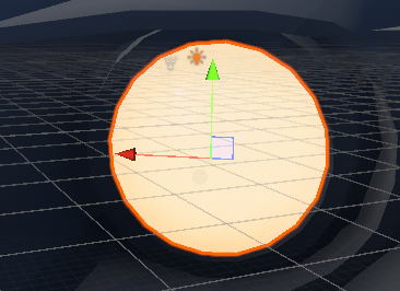
Mesh with Emission turned on.
Skidmarks
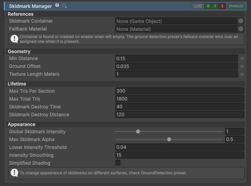
SkidmarkManager inspector.
Skidmarks are generated when wheel skids / slips over a surface.
- Skidmarks are achieved by procedurally generating a mesh. One mark consists of two triangles and the number of triangles per one section can be calculated as
Max Marks Per Section * 2. Min Distanceis the distance a wheel needs to travel before a new mark is created.- Default behavior is to delete the oldest triangles as soon as number of marks reaches
Max Marks Per Section- similar to the old snake game. To make this transition smoothFade Over Distancecan be enabled orPersistent Skidmarkscan be used. Check the section below for more info. - If skidmarks are not visible or clip into the terrain
Ground Offsetneeds to be increased. - To define when the wheel is slipping
Longitudinal Slip ThresholdandLateral Slip Thresholdfrom vehicle settings tab are used.
Surface-based Skidmarks
- Skidmarks use settings of currently active
SurfacePresetto get the settings for the current surface type.
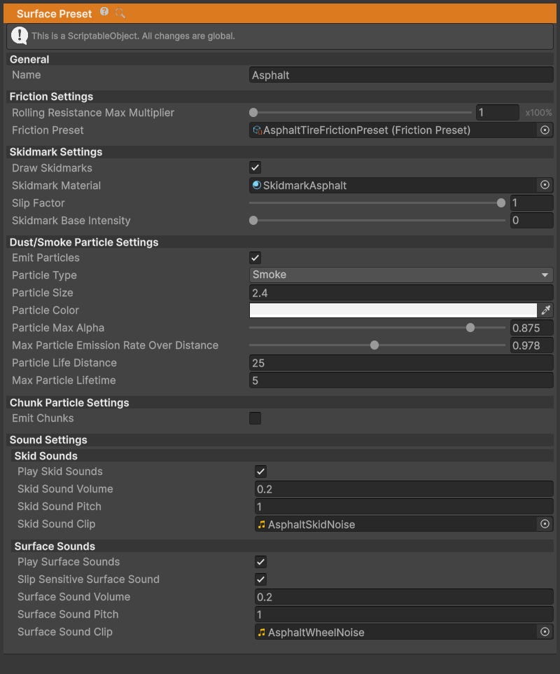
The asphalt SurfacePreset includes the skidmark settings.
- Also check GroundDetection page for more info.
Persistent Skidmarks
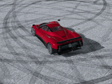
Persistent skidmarks enabled.
- Persistent skidmarks get stored into sections of
Max Marks Per Sectionsize. - Sections do not get destroyed as long as the player is within
Persistent Skidmark Destroy Distance. - Downside to this approach is that over time this will cause the number of triangles in the view-port to increase.
Surface particles
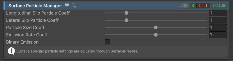
SurfaceParticleManager inspector.
SurfaceParticleManager creates and manages particles based on current SurfacePreset settings.
- Particles are emitted on per-wheel basis. Total surface particle count is a sum of particle counts from all the wheels'
ParticleSystems. Lateral Slip ThresholdandLongitudinal Slip Thresholdunder Settings tab determine the lowest wheel slip threshold needed for wheel to be considered to be slipping. This affects particle effects.
Mirrors
Mirrors are set up through a combination of Cameras, RenderTextures and Materials with specific UV mapping.
Camera first renders its view to a RenderTexture which is assigned to a Material(any shader that supports albedo map will work). This Material has an UV map that corresponds to the surface of the vehicle mirror.
Possible setups are:
- Render each mirror with a separate
Camerato a separateRenderTexturewhich is assigned to a separateMaterial. Best visual quality but slow. - Using UV map that is split between the mirrors which means that each mirror gets only a part of the UV map, but this comes at a disadvantage that the interior of the vehicle can not be seen in rearview mirror since the camera needs to start rendering at the rear of the vehicle to prevent intersection with the vehicle mesh.
- Hybrid approach: one camera for rearview mirror and one camera for left and right mirrors.
Ground detection
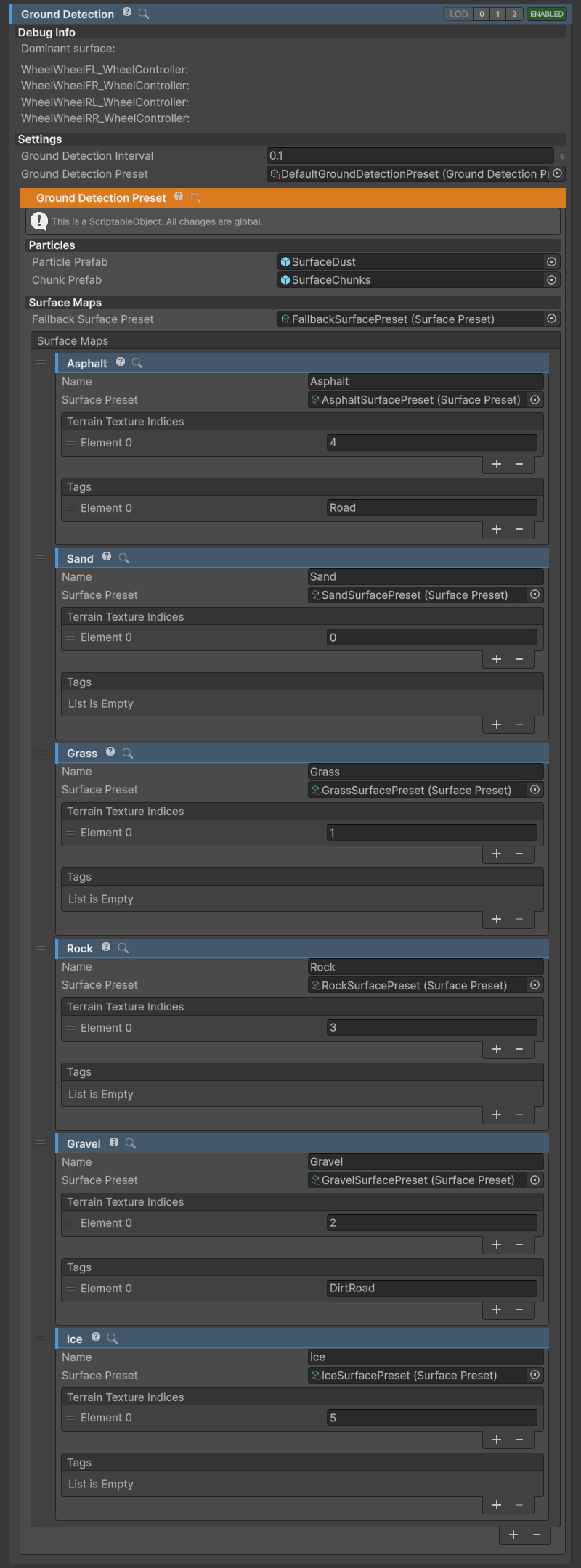
GroundDetection inspector.
GroundDetectionis one of the most important aspects of NWH Vehicle Physics. It determines whichFrictionPresetwill be used for calculating friction, which effects will be active, and which sounds will play. In short, it determines which wheel is on which surface.- Ground detection works based on
Terraintexture indices and object tags so it is very important how many textures there are assigned to theTerrainand in which order.
To prevent having to change the settings across all the vehicles GroundDetectionPreset ScriptableObject was introduced in NWH Vehicle Physics 2.
- NWH Vehicle Physics 2 supports ground detection with multiple
Terrains in one scene. In v14, ground detection checks all grounded wheels on a timer.Ground Detection Intervalsets the delay between checks; lower values react sooner at surface boundaries but cost more processing time. The wheel contact solver still runs separately at its own physics rate.
Assign a Fallback Surface Preset as well as the surface maps. It is used when no tag or terrain texture matches, and when ground detection is disabled by LOD. Choose a fallback appropriate to the scene so distant vehicles do not keep the last patch of ice or gravel indefinitely.
Ground detection preset
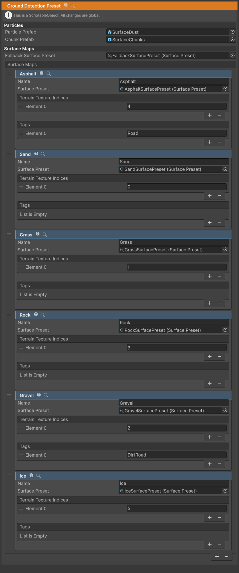
GroundDetectionPreset inspector.
GroundDetectionPreset is a ScriptableObject that determines which SurfacePreset will be used on which terrain texture and object. This is done through SurfaceMaps.
Assign it to the vehicle's Ground Detection section. Set its fallback surface, then add a surface map for each surface type. The same preset can be shared by all vehicles using those tags and terrain textures. The particle prefab references also belong to this asset.
Mapping surfaces
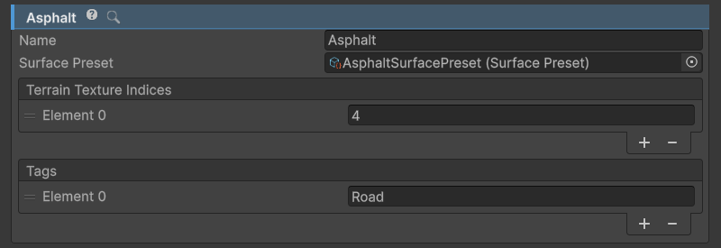
SurfaceMap inspector.
SurfaceMaptellsGroundDetectionwhichSurfacePresetto use for which terrain texture and/or object tag.GroundDetectionruns a check for eachWheelComponentto determine which surface thatWheelComponentis on. This is done by checking object tags first, then the dominant terrain texture. Within each check, maps are searched in list order and the first usable match wins. That map'sSurface Presetis assigned to the wheel.
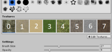
Terrain texture indices. Note that counting starts from 0.
Adding a New Surface Map
Adding a gravel SurfaceMap will be used as an example.
- Add a new
SurfaceMapby clicking on+button on the bottom of the list. - Check on which texture positions are the gravel textures. In the image above that would be 5 and 7. Add those numbers to the
Terrain Texture Indiceslist. - If there are objects that should represent gravel in the scene, assign a tag (e.g.
GravelRoad) to those objects and add it toTagslist.
Surface presets
SurfacePreset inspector.
SurfacePreset tells the VehicleController which settings to use for which surface.
This determines tire friction, the look of effects such as skidmarks and particle effects. It also changes sounds to match the surface.
Once set up, SurfacePreset can be used for different terrains, scenes or even across games since SurfacePresets do not carry any scene-specific fields.
Setup
- Right click on empty space in Project window and select Create > NWH > Vehicle Physics 2 > Surface Preset. This will create a new
SurfacePresetScriptableObjectin the current directory. - Assign a name to it for easier debugging later.
Friction
- Assign a
Friction Preset. This is aScriptableObjectwith settings for tire friction so thatWheelControllercan adjust its behavior according to the surface type. With asset come multipleFriction Presets so just pick one of those for now.
Skidmarks
- Adjust skidmark settings according to the surface type. More about skidmark settings on Skidmarks page.
Skidmark Materialwill be used on generated skidmarks while the wheel is on this surface type.Skidmark Intensitycontrols the mark left without slipping. Set it to 0 on a hard surface where a normally rolling tire should leave no mark; use a positive value on soft ground where rolling leaves a tire impression.
Dust/Smoke Particles
ParticleType-Smokeshould be used for hard surfaces (asphalt, concrete),Dustfor dusty surfaces (gravel, sand). The difference between the two is in the way the emission rates are calculated. IfSmokeis selected this will be related to the wheel slip while it will depend on vehicle speed forDust.Particle Life Distanceis used to calculateParticleSystem'sStart Lifetime. In v14 this is based on the wheel's longitudinal friction speed: faster slip shortens the lifetime, within the lifetime limits.Max Particle Emission Rate Over Distancedetermines amount of particles emitted over distance of one meter.Max Particle Lifetimecaps the calculated lifetime. Set it to 0 to remove the cap. At very low friction speed the calculated lifetime can be long, so use a positive limit unless that is intentional.
Sounds
SkidSoundandSurfaceSoundsettings are used to setWheelSkidComponentandWheelTireNoiseComponentSoundComponents values for current surface.
Rolling Resistance Max Multiplier increases the wheel's rolling resistance on this surface. Leave it at 1 for an unchanged tire setting; increase it for soft ground such as sand. Tune this along with the friction preset, since extra rolling resistance and reduced grip affect the vehicle in different ways.
Steering
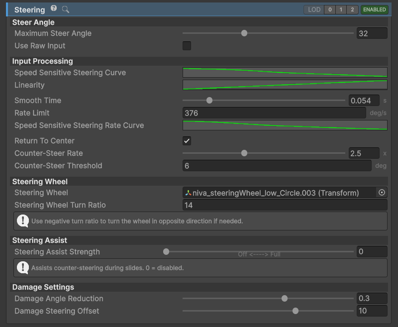
Steering inspector.
If the vehicle is not steering also check WheelGroup settings. It is most likely that all WheelGroups have SteerCoefficient set to 0 which means no axles will steer.
Fields
Maximum Steer Angle- angle in [deg] that the wheels can achieve. Multiplied by theWheelGroupSteerCoefficientto get the final axle steer angle.Use Direct Inputbypasses the steering component's input shaping. It still uses the vehicle input handler, so also set the handler's smoothing times to 0 when direct device response is wanted.Speed Sensitive Steering Curve- determines the steer angle coefficient in relation to speed. Useful for limiting steering at higher speeds to prevent spinning out.- X: Normalized speed (0 to 1) representing 0 to 50 m/s.
- Y: Steer angle coefficient by which the
Maximum Steer Angleis multiplied to get the final steer angle.
Speed Sensitive Smoothing Curvecontrols steering response in relation to vehicle speed.- X: Normalized speed (0 to 1) representing 0 to 50 m/s.
- Y: Steering rate multiplier, from 0 to 1. Lower values slow the steering response; return-to-center uses its own response.
Linearity- maps the steering input value (X) to the new output value (Y). Useful for making steering less sensitive around center point.Degrees Per Second Limit- an amount of degrees the steering can be turned in one second. Lower number for heavy machinery (e.g. 80), higher for sports car (e.g. 250).Return To Center- steering will return to center once the input is released.
Related
The input handler and steering component both affect the response. For keyboard control, first set a usable smoothing time, then reduce maximum angle at speed with Speed Sensitive Steering Curve. Counter Steer Rate Multiplier can make recovery from a slide faster without making ordinary steering equally abrupt.
Steering Assist Strength adds counter-steering during a slide; 0 disables the assist. This turns the wheels. The Arcade module can also apply artificial forces to the body, so tune those assists separately.
Brakes
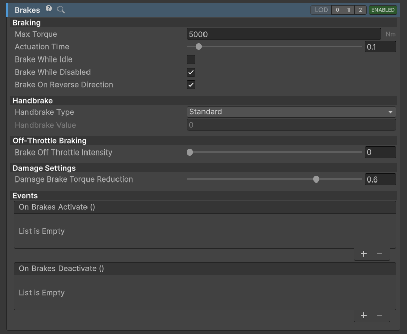
Brakes inspector.
Tips:
- Avoid using excessively high
Max Torqueas it might introduce jitter. Smoothingcan be used to make braking more progressive when using binary input.- To adjust the brake or handbrake bias between axles, check the WheelGroups.
Related:
Max Torque is the brake torque before the wheel group's brake coefficient is applied. If the rear wheels lock too early, reduce the rear group's coefficient rather than reducing braking on every wheel. The handbrake has its own coefficient per group; set it to 0 on axles that should not receive handbrake torque.
Damage
DamageHandler deforms the meshes on the vehicle. Skinned meshes are not supported. Add it to the vehicle root and enable Read/Write in the import settings of meshes that should deform. It uses a separate mesh instance for each vehicle.
Mesh deformation that is the product of crashing is queue based. This means that only a limited amount of mesh work is done per frame. Deformation Vertices Per Frame controls that budget. A higher value completes deformation in fewer frames, while a lower value stretches it over more frames and reduces frame drops. Adjust it on the device the final game will run on. One mesh is still processed when it exceeds the budget, so a single very dense mesh can cause a spike.
Deformation Radius sets the area around the impact and Deformation Strength sets how far vertices move for that impact. In v14, Falloff Type, Surface Conformance and Surface Angle Threshold shape the dent. Noise Strength adds irregularity; 0 gives a smoother result. Max Deformation Ratio limits extreme displacement relative to the radius.
The inspector retains the name Deceleration Threshold, but v14 compares it against collision relative speed multiplied by 100. Collision Timeout prevents repeated contacts from immediately producing another damage event. Collision Ignore Tags skips collisions with those objects, while Deformation Ignore Tags protects the tagged meshes on the vehicle. Wheel meshes are excluded from body deformation by default.
With Visual Only disabled, collisions also accumulate engine and transmission damage, and damage wheels close to the impact. This can reduce engine performance, lengthen shifts and affect the damaged wheels. Enable Visual Only if the vehicle should dent without these performance effects.
Vehicle settings
The Settings tab contains the vehicle's state settings, dimensions and setup validation. Before tuning handling, check that the model uses metres, the root scale is [1,1,1], and its local axes are X right, Y up and Z forward.
Set the dimensions to the vehicle's width, height and length in metres. They are used by systems such as aerodynamic drag. The dimensions gizmo helps check the values against the body; its offset only positions the display. Use Validate Setup and read the Console if the vehicle does not behave as expected.
Mass, center of mass and inertia have a large effect on handling. Set the Rigidbody mass to a plausible value for the vehicle. Unity 6 allows direct editing of center of mass and inertia; Variable Center of Mass is useful when mass should be calculated from the vehicle's parts or a changing load. Mass Affectors add those individual contributions.
Engine, exhaust and transmission sound positions are configured with the corresponding powertrain components in v14. Place them where the sound should originate on the model.
Lateral Slip Threshold and Longitudinal Slip Threshold control when visual effects and tire sounds regard a wheel as slipping. They do not change the tire's grip. To change grip, tune the active friction preset and StandardFriction; to change ABS or TCS intervention, tune that module.
For large maps, use Shifting Origin to keep physics close to the world origin. Test the vehicle near the edge of the intended map as well as at the starting point.
State settings and LOD
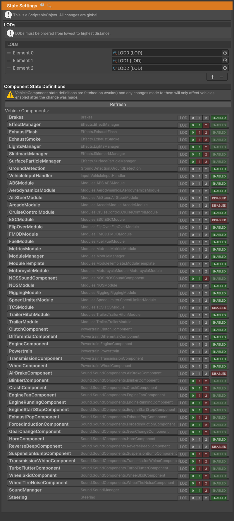
Example StateSettings.
- Each vehicle contains multiple
VehicleComponents, such asEngineComponentorGroundDetection. This includes the modules. Each of theVehicleComponentscan have a LOD setting and can be Disabled/Enabled. StateSettingsis aScriptableObjectcontaining info about LODs and Enabled/Disabled state of eachVehicleComponent. The aim ofStateSettingsis to prevent having to set the state of eachVehicleComponenton eachVehicleControllerindividually.- The
StateSettingscan be assigned through the Settings tab ofVehicleController.
Note
For more info about VehicleComponents and their states and LODs check VehicleComponent page.
LODs
Set the distance bands in the State Settings asset, then set the highest LOD index at which each component should remain available. For example, a sound component with index 1 can run at vehicle LOD 0 and 1, and is disabled at 2. An index of -1 excludes that component from LOD control.
The vehicle checks distance from its LOD camera periodically, about every 0.2 seconds. If no camera is assigned, it looks for Camera.main. In v14 the comparison is activeLODIndex <= state.lodIndex; the reverse comparison printed in older documentation was incorrect.
Order the distance bands from nearest to farthest. Each distance marks the far edge of that band; the last band also covers everything beyond it. For example, distances of 20, 50 and 100 metres give LOD 0 below 20 metres, LOD 1 from 20 to 50 metres, and LOD 2 beyond 50 metres. A small dead band around each boundary prevents rapid switching as the camera hovers near it.
LOD restores the components it disabled when the vehicle comes back into range. Components disabled in the asset or explicitly by a script remain off. Keep essential driving systems available at the distances where a vehicle must still simulate, and reduce sound and effects first. Test with the intended number of vehicles and check the Profiler to see what each distance band saves.
For split-screen or another multi-camera setup, assign each vehicle's lodCamera to the camera that should control its detail. A vehicle measures distance from one camera. If LOD does not update, check the assigned State Settings, the distance list and the camera reference. Scripts can read activeLODIndex and vehicleToCamDistance, or listen to onLODChanged to update their own effects.
State Definitions
- Each
VehicleComponentloads state fromStateSettings. This is only done once, on vehicle initialization, so theStateSettingscan also be thought of as initial vehicle component state settings. - Create an asset with Create > NWH > Vehicle Physics 2 > State Settings, then use Refresh to populate the component definitions. Set the initial enabled state and LOD index for each type. Refresh the definitions after adding a new component type.
Modules
NWH Vehicle Physics 2 is a collection of VehicleComponents. All aspects of it are a component - sound components, effect components, etc. - they all inherit from VehicleComponent. A module can be added or removed before initialization, so vehicles only need the optional behavior they use.
Modules carry over state system from the VehicleComponent which means that each module can be turned on or off, enabled or disabled or have LOD set.
Usage
- To add a module click on Add Component button at the bottom of the Inspector. Modules must be added to an object that already contains
VehicleController. - To add a module, add its wrapper to the vehicle:
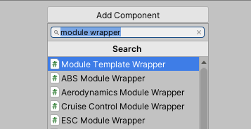
Adding a new module.
Module Wrapper
Each module is wrapped in a MonoBehaviour wrapper called ModuleWrapper. This is a way to get around lack of multiple inhertance in C#.
A module inherits from VehicleComponent and stores the vehicle behavior. Its wrapper inherits from MonoBehaviour, serializes the module and provides the component you add in the inspector.
Scripting
The following fragments assume the named vehicle or module reference and the corresponding module namespace are available in your script. Add or remove wrappers before vehicle initialization; enable or disable the existing module during play.
Adding a Module
Important
Adding modules after vehicle initialization is not supported! Consider adding the module before entering play mode or immediately after adding the VehicleController (from scripting), and keeping them Disabled until needed.
To add a module use:
myVehicleController.gameObject.AddComponent<MyModuleWrapper>();
Example (adding an ABSModule):
myVehicleController.gameObject.AddComponent<ABSModuleWrapper>();
Getting a Module
Modules are VehicleComponents wrapped in MonoBehaviour containers (wrappers).
MyModule module = myVehicleController.GetComponent<MyModuleWrapper>().GetModule() as MyModule;
Removing a Module
To remove a module use:
Destroy(myVehicleController.GetComponent<MyModuleWrapper>());
If doing this during the runtime the module should simply be disabled instead. ModuleManager does not update the modules list during the runtime so removing the module will result in an error.
Enabling/Disabling a Module
Since modules inherits from VehicleComponent they also work on the same principle:
myModule.VC_Enable(false);
myModule.VC_Disable(false);
Note
Set the LOD index to -1 when your script should control the module without distance checks. Otherwise, LOD can disable it outside its allowed range.
To disable LODs for a module use:
myModule.state.lodIndex = -1;
Creating a new module
Modules can be placed anywhere in the project and do not have to be in the same namespace as the included modules. Keep project-specific modules outside the package so an update does not replace them.
Each module needs its behavior class, a ModuleWrapper and a property drawer for the inspector. The included modules show this structure. Use a current module as the example for lifecycle signatures: v14 calls VC_Initialize(VehicleController), VC_Update(float) and VC_FixedUpdate(float). The old parameterless update examples are not valid in v14. See Scripting and architecture and the code upgrade notes for extension points.
Module manager
ModuleManager is a VehicleComponent that manages modules.
For more info on Modules check Modules page.
ABS
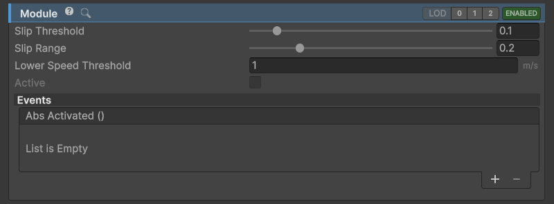
ABSModule inspector.
Anti-lock Braking System module.
Prevents wheels from locking up by reducing brake torque when slip reaches too high value.
The slip value above which ABS is activated can be adjusted through Slip Threshold. In v14 it is also capped below the active tire preset's peak slip, so raising the setting beyond that cap does not delay intervention. Slip Range controls how progressively brake torque is reduced.
Aerodynamics
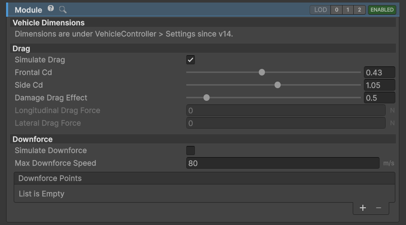
AerodynamicsModule inspector.
Calculates and applies aerodynamic drag and downforce.
Drag
- Drag depends on vehicle dimensions. Those can be adjusted under vehicle's Settings tab.
- Drag is calculated both in longitudinal and lateral directions. Intensity of drag can be adjusted through
Frontal CdandSide Cd(Cd = coefficient of drag) fields. Data for different vehicles is available here.
Downforce
Downforce is calculated in a simplified fashion by applying downforce to a number of points over the vehicle. In the simplest form a single downforce point at the center of the vehicle can be used, or one point at the front and one point at the end of the vehicle.
- Vertical position of
Downforce Points should be below theWheelControllerposition, or even as low as the floor of the vehicle. This is because all the force is applied in a single point which, if applied too high, can cause the vehicle to snap oversteer when changing direction. - Downforce is not dependent on vehicle shape or dimensions. It is calculated through
Downforce PointsandMax Downforce Speed. - Downforce increases with the square of speed from 0 to
Max Downforce Speedat which it reachesMax Forcevalue. - Enable Gizmos to be able to see downforce points (red sphere).
Cruise control
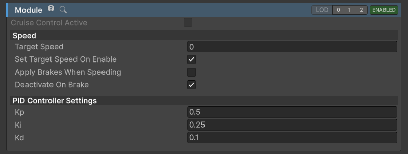
CruiseControl module.
Cruise Control implemented through a PID controller.
Target Speedvalue sets the speed that cruise control will try to achieve. Ignored in reverse.Can apply throttle and braking.
ESC
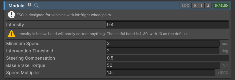
ESC module inspector.
Electronic Stability Control (ESC) module.
Applies braking on individual wheels to try and stabilize the vehicle when the vehicle velocity and vehicle direction do not match.
Motorcycles
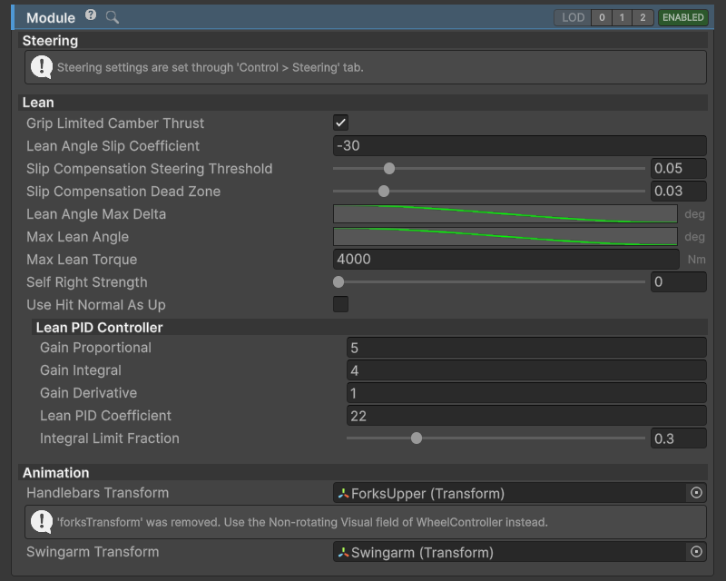
MotorcycleModule inspector.
Adds additional motorcycle balancing, steering and lean functionality to the NWH Vehicle Physics. The rest of the setup is similar to the conventional vehicle, just with two wheels and transmission outputting directly to the rear wheel, without the use of differentials.
Trikes can be implemented without this module as they do not require the additional functionality.
Field explanations can be seen by hovering over fields in the Unity inspector.
Arcade assistance
Module containing a collection of assists aimed at achieving arcade-like behavior from the vehicles.
Steer assist
Adds artificial steer torque to the vehicle, independent of the tire grip. This helps rotate the vehicle. Artificial Steer Strength controls its intensity; set it to 0 to disable it.
Drift assist
Prevents the vehicle from drifting over the set angle, helping prevent spin-outs. Target Drift Angle sets the starting limit. Steering and throttle contributions allow the driver to widen the drift. Drift Assist Strength and Max Drift Assist Force determine how strongly the rear of the vehicle is corrected.
Spin-out prevention
v14 also provides yaw damping through Spin Out Prevention and Max Yaw Rate. Counter-steer settings can reduce the assistance when the player is already correcting the slide. Start with the underlying vehicle driving well, then add these assists one at a time; otherwise one assist can hide the effect of another.
Flip over
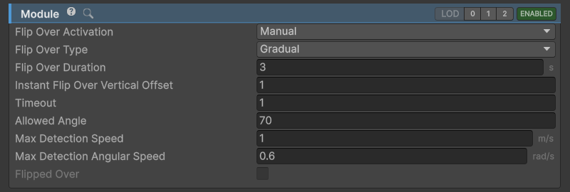
FlipOver module inspector.
If the vehicle gets flipped over FlipOverModule will flip it to be right side up again.
Flip Over Activationdetermines if the flip over will happen automatically, or if it will wait for userFlipOverinput once it detects that the vehicle is flipped over.Flip Over Typedetermines if the vehicle will get slowly rolled over or instantly flipped over in place.
Air steering

AirSteerModule inspector.
A simple module that adds ability for vehicles to steer while in air. This is achieved by adding a physics torque to the Rigidbody.
Fuel
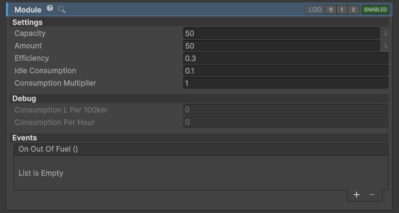
FuelModule inspector.
Module for simulating the fuel system in a vehicle. Fuel consumption gets automatically generated from engine efficiency (average ICE efficiency is used) and fuel energy content. Consumption can be adjusted through Consumption Multiplier.
- Prevents engine from running when out of fuel.
Amountindicates the amount of fuel currently in the tank whileCapacityindicates maximum tank capacity.
Metrics
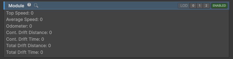
MetricsModule inspector.
MetricsModule is used to record data about vehicle behavior. That data can then be used for display purposes, achievements or e.g. a boost system using NOS.
NOS
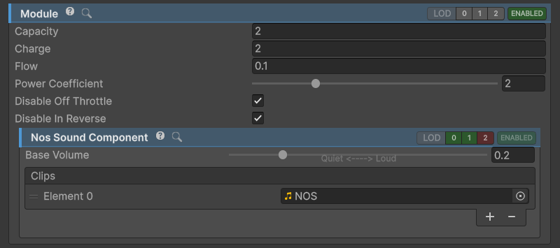
NOSModule inspector.
NOS (Nitrous Oxide System) module.
- Adds power to the engine.
- Has its own
SoundComponentwhich imitates hiss caused by releasing highly pressurised NOS from the bottle. - If
ExhaustFlasheffect is enabled it will be active while NOS is active.
Set the bottle Capacity and Charge in kg and Flow in kg/s. Their ratio determines how long boost can last. Power Coefficient multiplies engine power while NOS is active. The old engine-volume and exhaust-emission coefficients are retained in serialized data but do not drive those effects in v14.
Rigging
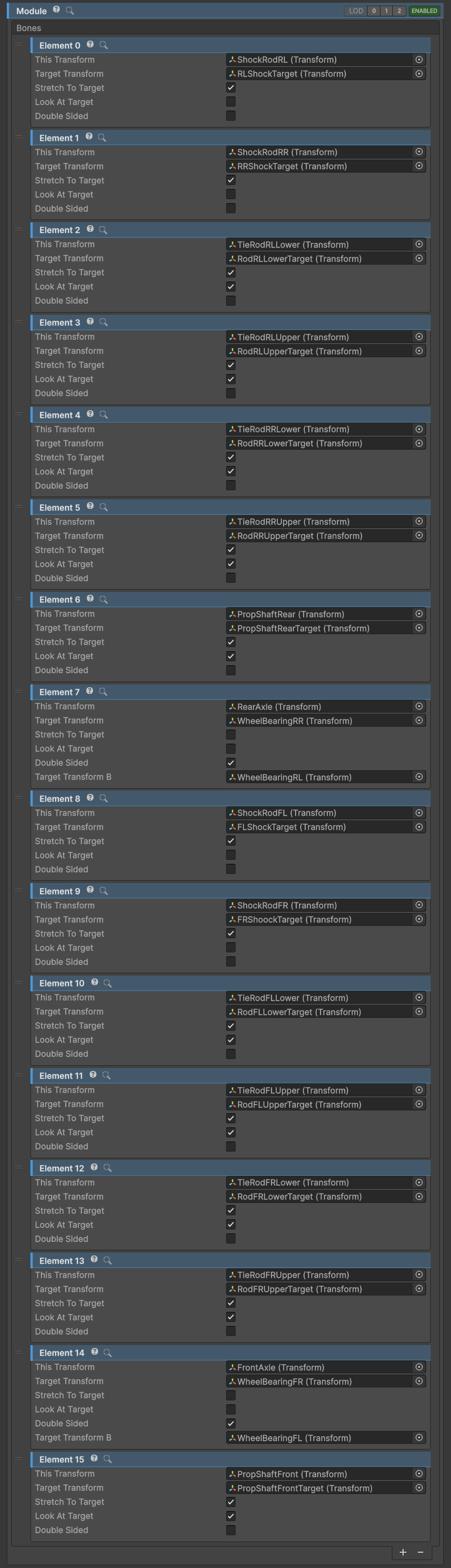
RiggingModule inspector.
Module used to animate rigged models by moving the axle/wheel bones.
Axle Bones- list of handles controlling the axle bones. Each item is a single axle handle.Wheel Bones- list of handles controlling the wheel bones. Each item is a single wheel bone handle.
Speed limiter

SpeedLimiter module inspector.
Module that limits vehicle speed to the set speed limit.
Only limits throttle application, does not apply brakes. For that use CruiseControlModule.
Traction control
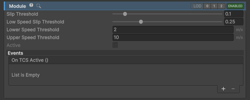
TCSModule inspector.
Traction Control System (TCS) module. Reduces engine throttle when excessive slip is present.
Trailer module
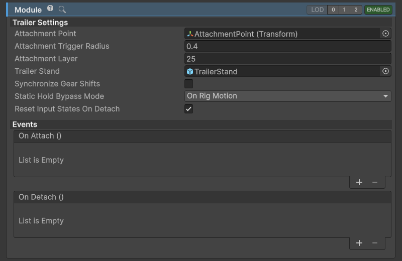
TrailerModule inspector.
TrailerModule works in tandem with TrailerHitchModule. VehicleController that has TrailerModule is able attach to a VehicleController that has TrailerHitchModule.
- One vehicle can have both
TrailerHitchModuleandTrailerModule. Attachment Pointis the point at which the trailer will be attached to the towing vehicle. The script creates a SphereCollider trigger at this point which detects if the TrailerHitchModuleAttachment Pointis nearby.Attachment Pointneeds to be a child of theGameObjectcontaining theTrailerModule.Trailer Standis the object which will be enabled if the trailer is detached and vice versa. It prevents the trailer from tipping forward on trailers with only the back axle.- If
Synchronize Gear Shiftsis enabled the trailer object will be kept in the same gear. This allows for powered trailer or vehicles that are constructed out of two Rigidbodies.
Also check Trailer Hitch module.
For the complete towing setup, follow the Trailers guide.
Trailer hitch
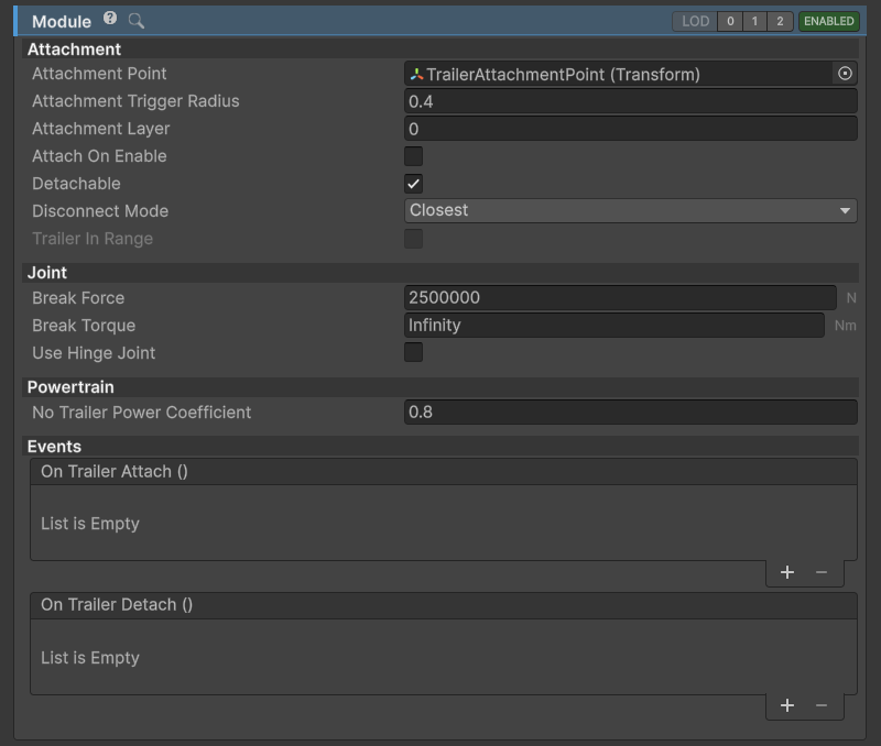
TrailerHitch module.
VehicleController with TrailerHitchModule can attach a VehicleController with TrailerModule as a trailer.
- Both
TrailerHitchModuleandTrailerModulecan be present on one vehicle at the same time. AttachmentPointis the point at which the trailer will be attached. The trailer will be moved so that both trailer and hitchAttachmentPoints are at the same position. This is where the physics joint gets created.Attachment Pointneeds to be a child of theGameObjectcontaining theTrailerHitchModule.- On initialization a SphereCollider trigger is created at the attachment point. This is used to detect if a TrailerModule is nearby. When there is overlap between the
TrailerModuleandTrailerHitchModuletriggers, pressing 'T' (default key mapping) will connect the trailer.
Also check Trailer module.
For the complete towing setup, follow the Trailers guide.