Airfoil
Handles aircraft-air interaction. Sliced into sections (AirfoilSection) that simulate individually using 2D airfoil principles.
Warning: Large maps (> ~4000 units) require floating origin. Floating Origin in Unity.
Geometry
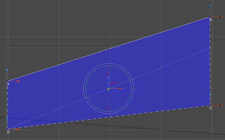
- Trapezoidal shape with corners A, B, C, D (clockwise from top-left)
- Corners adjustable on Y-plane (2D X-Z position) via blue-red handles
- Position/rotation adjusted with standard handles
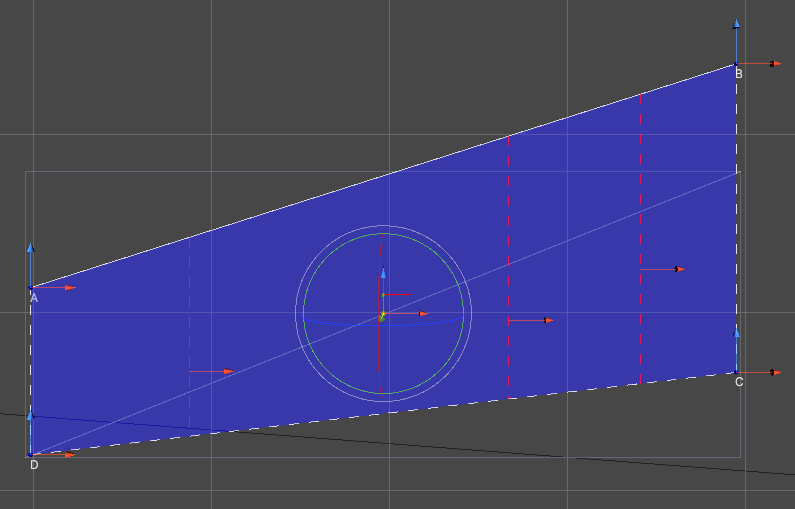
- Sliced along red dashed lines via Slice button into
AirfoilSections - Each section simulated separately during play
Shape
2D trapezoidal plane with position/rotation relative to parent Transform. Adjusted via A, B, C, D handles. AD and BC lines stay parallel.
For complex shapes, use multiple Airfoils per object. Best practice: one object and one Airfoil per flight surface.
Slicing Planes
- Slice
Airfoilinto smaller sections (dashed red gizmos) - Position adjustable via red handles
- Auto-generated; adjust count via
Slice Count+ Generate Slicing Planes
Sections
Press Slice to generate AirfoilSections (green lines, named S[number]).
Check orientation indicators:
- Blue (forward): Towards incoming air
- Red (right): Flush with airfoil, towards B-C line
- Green (up): Up from airfoil plane
If green points wrong way, press Flip.
Position and Rotation
Adjust Airfoil plane position/rotation relative to parent Transform using handles (similar to Transform handles).
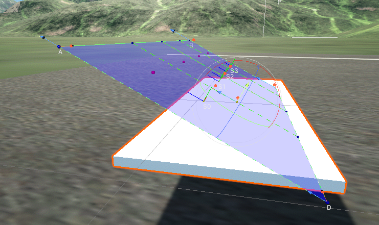
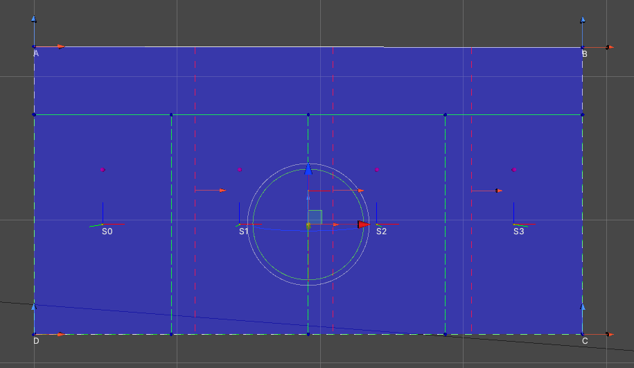
Gizmos and Handles
- A, B, C, D - Airfoil corners
- Green dashed lines - AirfoilSections
- S0, S1, S2, S3 - Section names
- Blue, green, red lines - Section orientation (forward, up, right)
- Red dashed lines - Slicing planes (adjustable via red arrow handle)
- Position/rotation handles - Adjust airfoil relative to Transform
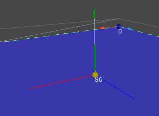
- Yellow sphere - Current airfoil position
- Purple spheres - Aerodynamic center of each section
Setup
Example using cube [5, 0.1, 2]:
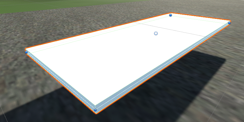
Add Airfoil component. Auto-matches mesh dimensions and orientation:
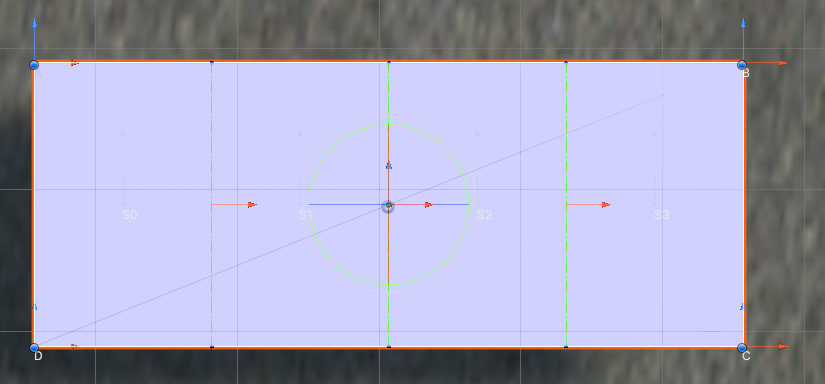
Auto-performs: Orientate To Mesh, Fit To Mesh, Generate Slicing Planes, Slice. Press Auto to repeat.
Manual setup:
- Reset: Reset to 1x1 default
- Orientate To Mesh: Match mesh orientation (may fail for non-wing shapes)
- Fit To Mesh: Position corners to match mesh
- Generate Slicing Planes: Create/adjust slicing planes
- Slice: Generate AirfoilSections
Mirroring: Assign opposite wing to Mirroring Target, press Mirror to copy setup.